File:ACKsess 6.jpg
Size of this preview: 800 × 600 pixels. Other resolutions: 320 × 240 pixels | 1,280 × 960 pixels.
Original file (1,280 × 960 pixels, file size: 154 KB, MIME type: image/jpeg)
Summary
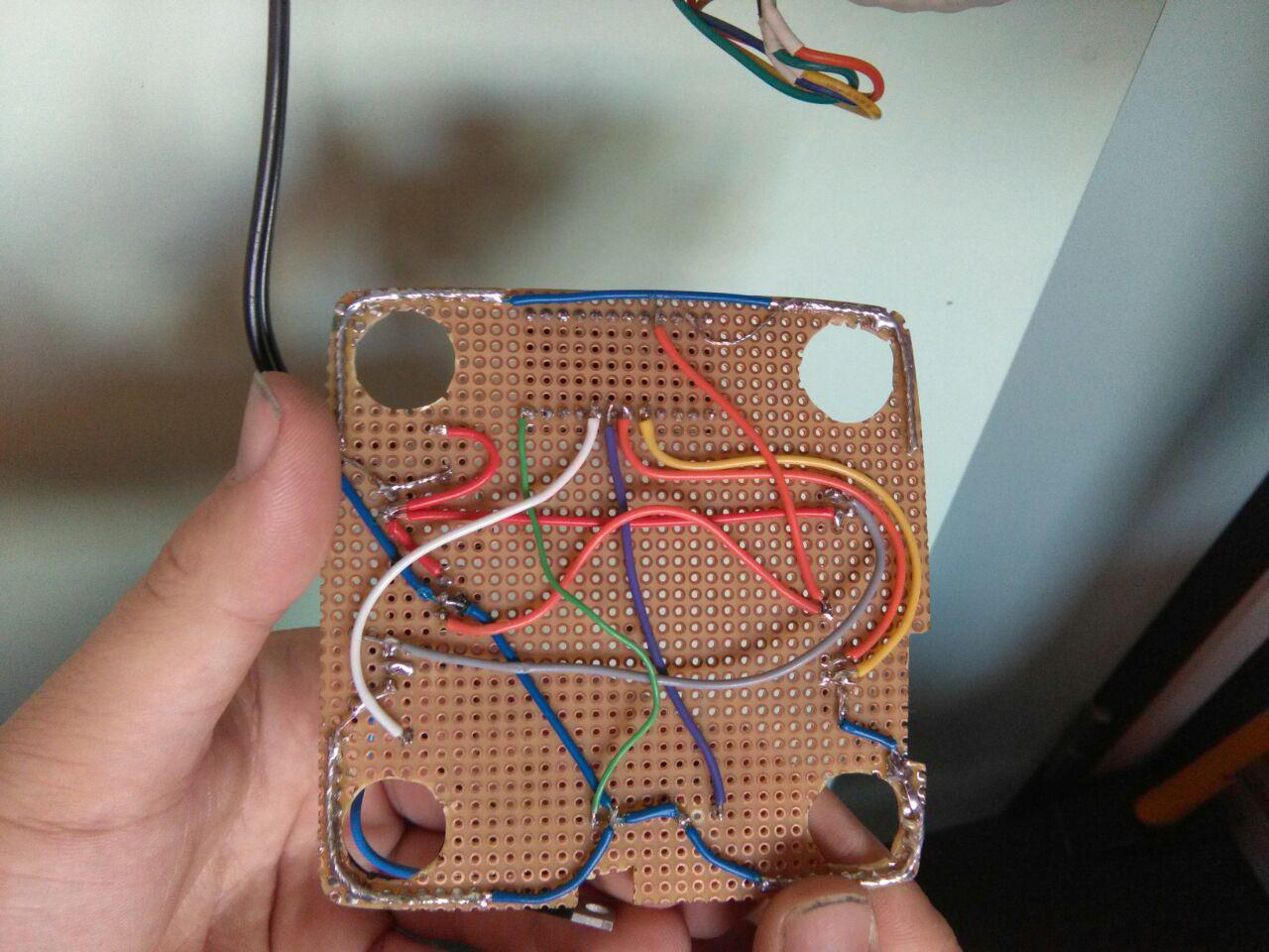
PCB that fits in the Joystick to open the door.
- at the top, the footprint of the Arduino Pro mini can be seen (with its used pins, mirrored)
- top row, orange: 5V
- top row, blank: GND
- pin 2, yellow: reader (onewire)
- pin 3, orange: LED (onewire)
- pin 4, purple: Firebutton
- pin 5, white: relay (transistor)
- pin 9, green: buzzer
- at the left, the 12V power supply comes in
- at the right, the relay output (gray) and iButton connector + led is established (yellow+orange)
- blue/blank: GND
Licensing
You are free to
- Share — copy and redistribute the material in any medium or format
- Adapt — remix, transform, and build upon the material
for any purpose, even commercially. The licensor cannot revoke these freedoms as long as you follow the license terms.
Under the following terms
- Attribution — You must give appropriate credit, provide a link to the license, and indicate if changes were made. You may do so in any reasonable manner, but not in any way that suggests the licensor endorses you or your use.
- ShareAlike — If you remix, transform, or build upon the material, you must distribute your contributions under the same license as the original.
See also: creativecommons.org/licenses/by-sa/3.0/
File history
Click on a date/time to view the file as it appeared at that time.
| Date/Time | Thumbnail | Dimensions | User | Comment | |
|---|---|---|---|---|---|
| current | 16:44, 9 February 2017 | | 1,280 × 960 (154 KB) | Xopr (talk | contribs) | PCB that fits in the Joystick to open the door. * At the top, the footprint of the Arduino Pro mini can be seen (with its used pins, mirrored) * At the left, the power supply comes in * At the right, the iButton connector + led is established |
- You cannot overwrite this file.
File usage
The following page links to this file: