Difference between revisions of "DTS Coherent Acoustics encoder"
(→Frame structure) |
(→PCB design) |
||
| Line 57: | Line 57: | ||
== PCB design == | == PCB design == | ||
| + | |||
| + | To implement the workings of the encoder, an FPGA is used to format the incoming data, and to assemble the outgoing data packet. All the transforming and coding of the individual audio channels, a DSP processor can be used, as it is optimized to work with accumulation, multiplication and other procedures to work with digital systems such as FFT. Because we would have to have a very fast DSP processor to calculate all the individual channels of the stream, workload is divided into several DSP processors. For future development, up to 16 DSP's can be used for processing. | ||
The following artwork of the PCB has been created to test the workings of the encoder: | The following artwork of the PCB has been created to test the workings of the encoder: | ||
[[File:DTSPCB.PNG]] | [[File:DTSPCB.PNG]] | ||
Revision as of 09:02, 9 August 2013
| Project: DTS Coherent Acoustics encoder | |
|---|---|
| Featured: | |
| State | Stalled |
| Members | Danny Witberg |
| GitHub | No GitHub project defined. Add your project here. |
| Description | Make my own DTS encoder |
| Picture | |
| No project picture! Fill in form Picture or Upload a jpeg here | |
This project descibes a possible hardware implementation of a DTS Coherent Acoustics Core Audio encoder. The DTS Coherent Acoustics coding system is used as a file format for playing multichannel digital audio, but also for transporting multichannel audio over a digital audio connection. It is frequently used as the preferred CODEC in movies on DVD, Bluray or downloadable format. The coding system offers an exsensible high quality compressed multichannel audio stream. The core stream has a maximum of 7 channels of fullband audio, with 1 low frequency effect channel, and a resolution of 24 bits and a sample rate of 48kHz. Apart from this core audio stream, an extended stream can be offered with additional channels and/or higher sampling rates. A decoder for the datastream must be able to decode the core stream, but decoding the extended is optional. This way, backwards compatibility is provided. The extended stream can contain up to 32 fullband channels, frequency extension for core audio streams as well as extended audio streams, and resolution enhancements for all channels up to lossless quality.
This project describes the hardware implementation of a core audio stream encoder, using an FPGA and Digital Signal Processors. It accepts up to 4 stereo SP/DIF digital audio connections, or a single ADAT multichannel stream, and converts it to the DTS compressed audio link. If you plan to use this project for anything other than personal education, you should ask DTS Inc. if you have to obtain a licence: http://www.dts.com/professionals/licensing.aspx
Contents
How the DTS Coherent Acoustics CODEC works
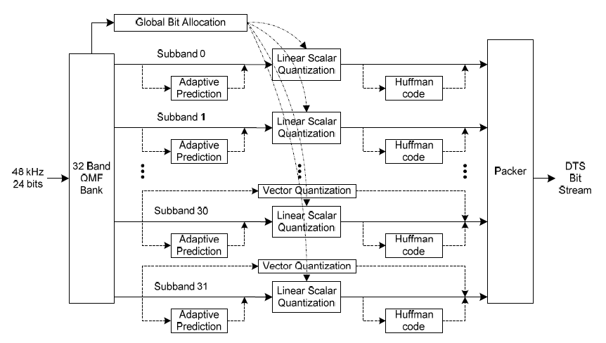
A fullband channel is compressed in various ways, but always begins by dividing the channel into 32 subbands by means of a quadrature mirror filter. After obtaining these 32 subbands, every subband can, but does not have to be, compressed with use of a adaptive differential method, also named ADPCM. This algorithm is used to send the difference that the signal has, compared to the previous sample, instead of the actual amplitude. In slow changing signals, low frequencies, this can be a very effective method to reduce the amplitude of the signal that has to be encoded. After this first step, linear scalar quantization is used to compress the amount of data that has to be transmitted. In other words, a clevery chosen lookup table is used to descibe the amplitude of the signal. After this quantization, the data may be further compressed by use of a huffman code. Finally, the remaining data is placed in the core audio stream.
The Quadrature Mirror Filter (QMF)
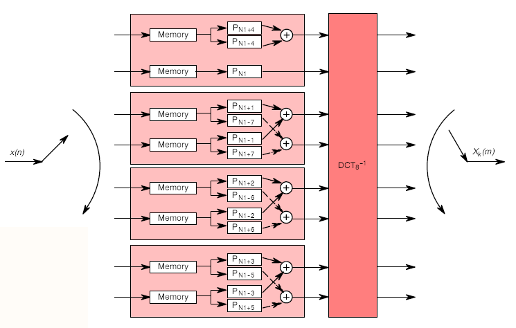
The quadrature mirror filter or QMF filter is a set of filters, which complements each other to filter a frequency range into a number of subsets. After recomposition, the result reconstructs or closely reconstructs the original. The most effective way to do the required 32 band QMF is by using a FFT or Fast Fourier Transformation. The process begins by rearranging the samples in order to obtain the complementing nature of the filter. After this process, an IDCT transformation is implemented with an FFT routine. In modern DSP processors, this FFT routine is greatly optimized and can be executed quite fast. The process if visualized with the following example, for a QMF filter of 8 subbands:
Adaptive Differential Pulse Code Modulation
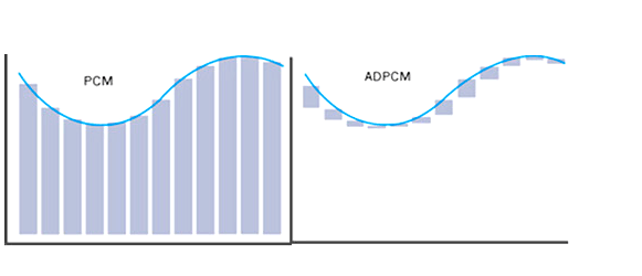
The subband output of the QMF filter can be encoded using an ADPCM scheme, and can help reducing the amount of data that has to be encoded. The principle is that instead of the actual amplitude of the signal is encoded, the difference is encoded instead. This can be a great help in reducing the stream data, if the input signal does not alter that much from sample to sample. In subband samples, this is likely to be the case. It is measured by encoding the input samples with the ADPCM scheme, and then comparing it to the original. If the so called prediction gain is high enough, the samples can then be converted using ADPCM.
Quantization
Quantization in digital signal processing, is a process of converting a number of input samples into a smaller number of output samples. A normal analog to digital converting proces is an everyday example of such a process. The analog signal, representing an infinite number of possible values, are converted into a given number of output signals, thus digitizing the input signal. In case of the mid tread linear scalar quantization used in DTS, the 24 bit input signal is converted in a 6 or 7 bit output signal. The way these converting tables work is logarithmic, because the perceptive hearing of the human ear is also logarithmic. Small differences in values can be encoded with a greater precision than larger ones. With a 6 bit table, there are 2.2 decibels per step, and half that in case of a 7 bit table.
Huffmann encoding
If a bitstream has to be further compressed, the now quantized signal can be further reduced with use of a Huffmann encoder. Without going into all the details, a lookup table is used to reduce the outgoing stream. The output stream can vary in length, because input bit patterns that occur more frequently are encoded with fewer bits than less frequent occuring bit patterns. An example of this is the written language. In english, the letter E is more likely to occur in a sentence then, for example, the letter Q. Thereby, the E can be encoded with a shorter bit pattern. As long as the input of the data has this predictive nature, a Huffmann encoder can help to compress the data.
Frame structure
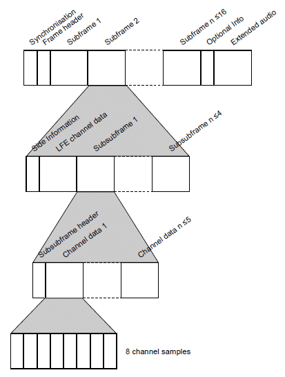
A DTS Coherent Acoustics datastream is a sequence of frames. All of these frames contains the following fields:
- Synchonisation pattern. The sync pattern is always 0x7ffe8001
- Header. This contains general data about the frame, how many sample blocks it contains, overall size, audio channel arrangment etc.
- Subframes. These contain the actual core audio data. Up to 16 subframes can be packed into one frame
- Optional information. Timecode and downmix coefficients are some examples of optional data
- Optional extended audio. Up to 2 more channels, as well as sample frequency extensions can be placed. Decoding of this is optional, but the decoder must recognize the existence of the extended audio
The Subframes containing the audio data is built up as follows:
- Side information. All data used to decode the frame is placed in here. The used Huffmann code tables, whether or not ADPCM is used, what scale is used for quantization
- LFE data. The Low Frequency Effect data is stored here, and is not encoded in the same way as fullband channels
- Up to 4 subsub frames with fullband channel data
PCB design
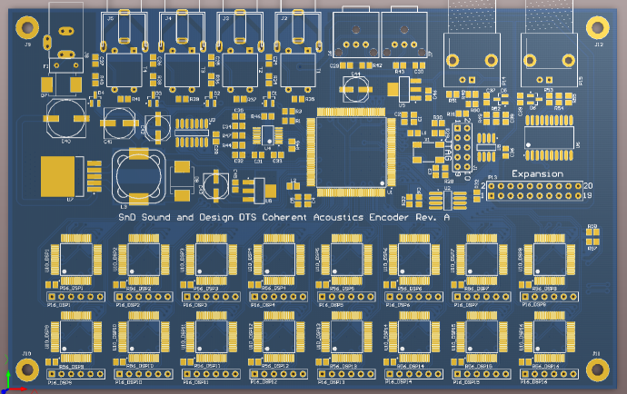
To implement the workings of the encoder, an FPGA is used to format the incoming data, and to assemble the outgoing data packet. All the transforming and coding of the individual audio channels, a DSP processor can be used, as it is optimized to work with accumulation, multiplication and other procedures to work with digital systems such as FFT. Because we would have to have a very fast DSP processor to calculate all the individual channels of the stream, workload is divided into several DSP processors. For future development, up to 16 DSP's can be used for processing.
The following artwork of the PCB has been created to test the workings of the encoder:
