Difference between revisions of "ESP-2"
(replaced todo) |
|||
| Line 14: | Line 14: | ||
* Added resistor to the 5V ESP^2 TX signal (should be two diodes I guess, the resistor divider didn't work) | * Added resistor to the 5V ESP^2 TX signal (should be two diodes I guess, the resistor divider didn't work) | ||
| − | == | + | == ESP-12 == |
| − | + | Note that there are adapter board that give the ESP-12 a 0.1" pitch and includes the necessary resistors. | |
| + | It would be handy, however, to have an adapter/socket like [http://www.ebay.com/itm/282505793123 this] or [https://www.thingiverse.com/thing:2163441/ this] with [http://www.ebay.com/itm/132235141457 these] | ||
Location: [[Location::hACKspace]] (in the right 'solder cabinet') | Location: [[Location::hACKspace]] (in the right 'solder cabinet') | ||
[[Category:ESP8266]] | [[Category:ESP8266]] | ||
Revision as of 14:19, 19 July 2017
| Project: ESP-2 | |
|---|---|
| Featured: | |
| State | Completed |
| Members | Prodigity |
| GitHub | No GitHub project defined. Add your project here. |
| Description | Playing around with cheap wifi modules |
| Picture | |

| |
synopsis
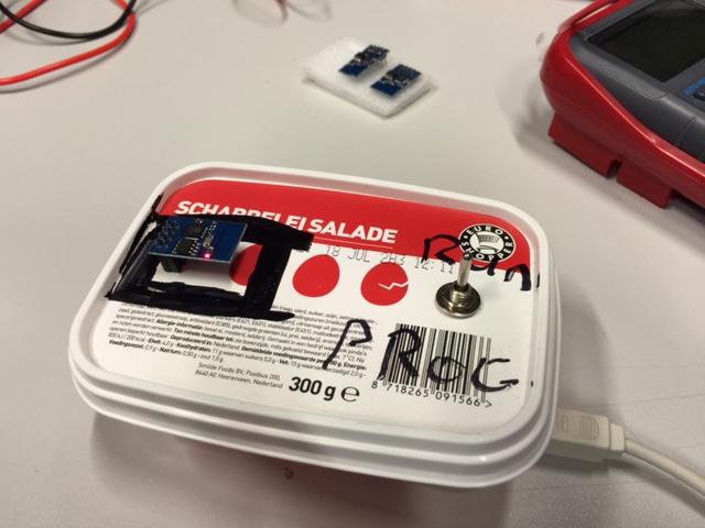
To make the ESP8266 more accessible to everyone Prodigity has created a "programmer" which allows for easy firmware uploading and communication with the ESP-01 module.
Revision 1.1
xopr Modified the ESP^2 a bit:
- Added three wires (VCC, GND and GPIO2) for Dallas temperature sensor debugging (wire ends are insulated)
- Added pullup resistor was added so GPIO0 can be used after the device has been booted
- Added resistor to the 5V ESP^2 TX signal (should be two diodes I guess, the resistor divider didn't work)
ESP-12
Note that there are adapter board that give the ESP-12 a 0.1" pitch and includes the necessary resistors. It would be handy, however, to have an adapter/socket like this or this with these
Location: hACKspace (in the right 'solder cabinet')