Difference between revisions of "Automatic window blinds"
(→relay box) |
m (removed outdated message (it annoyed me)) |
||
| (8 intermediate revisions by 4 users not shown) | |||
| Line 1: | Line 1: | ||
{{Project | {{Project | ||
| − | |State= | + | |Featured=No |
| + | |State=Impossible | ||
|Members=xopr | |Members=xopr | ||
|Description=Connect and interface the existing window blinds | |Description=Connect and interface the existing window blinds | ||
| + | |Picture=Windowblinds_motor_pcb.jpg | ||
}} | }} | ||
| − | == disclaimer == | + | == disclaimer == |
| + | |||
{{InfoBox | {{InfoBox | ||
| − | |Title=NOTE: The first blind | + | |Title=NOTE: These window blinds were located in the very first space where we moved out of in 2012 |
| − | + | }} | |
| − | + | ||
| + | == intro == | ||
| + | |||
| + | The first space had 8 windows with a width of a little less than 1.80m per window, each with a motorized window blind mechanism. This would be an opportunity to automate this system to our needs. | ||
| + | |||
| + | Last time, [[User:Eracoon|eracoon]] and [[User:Coolepascal|CoolePascal]] were helping out, so they deserve credits here (correct [[User:Xopr|xopr]] if I'm wrong :) | ||
| + | |||
| + | == the project == | ||
| + | |||
| + | The stuff worked more or less. Now it's time to optimize/automate. | ||
| − | + | Some ideas to work out: | |
| − | |||
| − | |||
| − | + | *Control it with [http://www.arduino.cc/ Arduino]+[http://www.arduino.cc/en/Main/ArduinoEthernetShield Ethernet Shield] or [http://shop.myavr.com/index.php?sp=article.sp.php&artID=100065 MyEthernet] | |
| − | + | *Put on the letters ACKspace | |
| + | *Make the blinds individually controllable | ||
| + | *Install a string of individually controllable LED strings on each blind, making the windows a mini-Blinkenlights array. | ||
| + | *your creativity here | ||
| − | == | + | == specs == |
| − | |||
| − | |||
| − | + | Unfortunately, the cables are cut, probably somewhere in the basement, by estimating where the signaling cable leaves; you can see the white cable going into the metal conduit on the far right side of the windowed wall. It then goes down left of the second last concrete pillar, where it disappears. | |
| − | + | Each blind has its own transformer right behind the motor on the right side of the window, labeled as a 12v 1.3A (it's an unstabalized one), which plugs into the system as a 3.5mm jack plug (be *careful when unplugging* this, because jack plugs short momentarily) | |
| − | |||
| − | + | === console === | |
| − | |||
| − | |||
| − | |||
| − | |||
| − | |||
| − | + | [[Image:Windowblinds console front.jpg]] [[Image:Windowblinds console back.jpg]] | |
| − | |||
| − | + | The buttons work as followed: | |
| − | + | *^-.- Rotate left (keep small opening but block sun) | |
| − | + | *-.-^ Rotate completely right, closing the blinds | |
| − | + | *<||> Rotate and open blinds/stops actions upon release | |
| + | *|><| Rotate and close blinds/stops actions upon release | ||
| − | + | === relay box === | |
| − | |||
| − | |||
| − | |||
| − | |||
| − | + | [[Image:Windowblinds relay box.jpg]] | |
| − | [[ | ||
The turn left/right buttons were extended to a relay box | The turn left/right buttons were extended to a relay box | ||
| − | (come to think of it, they start rotating upon a pulse, which will eventually close them, so this setup is at least peculiar.) | + | (come to think of it, they start rotating upon a pulse, which will eventually close them, so this setup is at least peculiar.) [[User:Stoney3K|Stoney3K]] suggests this setup is a cross-linked set of 12VDC relays in a set/reset flip-flop configuration, meaning the relay will latch when you push the 'close' button, but release once power is disengaged through the motor control or end stop switch. |
| − | [[User:Stoney3K | Stoney3K]] suggests this setup is a cross-linked set of 12VDC relays in a set/reset flip-flop configuration, meaning the relay will latch when you push the 'close' button, but release once power is disengaged through the motor control or end stop switch. | + | |
| + | This unit is missing a (fairly common, 12VDC) power supply. The current rating is marked on the socketed relays. | ||
| − | + | === blinds === | |
| − | + | The blinds open up from the center. Note that the string at window 4 is fubar: better not use the open function because you won't be able to close it anymore. To demount the blinds, do the following | |
| − | The blinds open up from the center. | ||
| − | To demount the blinds, do the following | ||
| − | |||
| − | |||
| − | |||
| − | |||
| − | |||
| − | |||
| − | |||
| − | + | *unplug the power supply | |
| − | + | *unplug the jack connector and box headers | |
| + | *with grace, bend the plastic sheets 45° towards you, use a fingernail to open up the clip a bit, and you'll be able to remove the sheet easily | ||
| + | *repetition is inevitable | ||
| + | *press firm on each of the two metal clips on the back of the rail, while holding that ;) | ||
| + | *.. | ||
| + | *profit! | ||
| − | + | === motor unit === | |
| − | The top | + | The blinds signaling system uses a daisy-chaining plug-on module (it's two double sided prints soldered on top of each other) with two 10 pins box headers (see picture). |
| − | [[ | + | [[Image:Windowblinds chain module.jpg]] |
| − | The PCB has several easy identifyable components on it, for example: | + | The top connector (close to the ceiling) is used as input, while the bottom header is connected to the next set of blinds. |
| − | *a PIC processor (the big IC with the sticker) | + | |
| − | *a motor driver IC (most likely [http://en.wikipedia.org/wiki/H_bridge H-bridge], that silly looking IC) | + | [[Image:Windowblinds motor pcb.jpg]] |
| − | *a [http://en.wikipedia.org/wiki/Rectifier voltage rectifier], the big black thing below the shiney capacitor | + | |
| + | The PCB has several easy identifyable components on it, for example: | ||
| + | |||
| + | *a PIC processor (the big IC with the sticker) | ||
| + | *a motor driver IC (most likely [http://en.wikipedia.org/wiki/H_bridge H-bridge], that silly looking IC) | ||
| + | *a [http://en.wikipedia.org/wiki/Rectifier voltage rectifier], the big black thing below the shiney capacitor | ||
*a [http://en.wikipedia.org/wiki/Voltage_regulator voltage regulator] LM series (not LM317 though, can't remember), the small black thing below the shiney capacitor | *a [http://en.wikipedia.org/wiki/Voltage_regulator voltage regulator] LM series (not LM317 though, can't remember), the small black thing below the shiney capacitor | ||
| − | Also, the unit has two DC motors and 4 end-detectors (microswitches) | + | Also, the unit has two DC motors and 4 end-detectors (microswitches) |
| + | |||
| + | === pinout === | ||
| + | |||
| + | Warning: colors are not verified yet, but are plausible to be correct. The current colors might need swapping in pairs of two, due to the layout of the box header. | ||
| + | |||
| + | Also, timings can be off, but are reasonable guidelines. | ||
| + | |||
| + | From the relay box, the rightmost relay connecting the blue and orange wires do the 'clockwise' turning, while the second right one (using white and brown wires) do 'counter clockwise'. | ||
| + | |||
| + | All pinouts are connector side, not print side | ||
| + | <pre>Daisy chain pin socket (both are similar, but some pins might not be 'chained' | ||
| + | 2 10 | ||
| + | .-----. | ||
| + | |:::::| | ||
| + | '-- --' | ||
| + | 1 9 | ||
| + | |||
| + | Main controller pin socket | ||
| + | 2 18 | ||
| + | .---------. | ||
| + | |::::: :::| | ||
| + | '-- ------' | ||
| + | 1 17 | ||
| − | + | Box header (cables and remote) | |
| − | + | 1 10 | |
| + | .-----. | ||
| + | |:::::| | ||
| + | '--_--' | ||
| + | 2 8 | ||
| + | </pre> | ||
| + | <br> | ||
| − | + | {| class="wikitable" | |
| + | |+ window blind control layout | ||
| + | |- | ||
| + | ! scope="col" | pin | ||
| + | ! scope="col" | color | ||
| + | ! scope="col" | indicator | ||
| + | ! scope="col" | function | ||
| + | ! scope="col" | remark | ||
| + | |- | ||
| + | | 1 | ||
| + | | white | ||
| + | | V<sub>IN</sub> | ||
| + | | unsure; possibly to power the driver IC | ||
| + | | driver side: connected through the 8-pin jumper in the daisy-chain module,<br>remote side: connected with pin 2 | ||
| + | |- | ||
| + | | 2 | ||
| + | | brown | ||
| + | | V<sub>IN</sub> | ||
| + | | unsure; possibly to power the driver IC | ||
| + | | driver side: connected through the 3-pin jumper in the daisy-chain module,<br>remote side: connected with pin 1 | ||
| + | |- | ||
| + | | 3 | ||
| + | | green | ||
| + | | template broken?{{!}} {{!}}> <{{!}} | ||
| + | | rotates to 20°(CCW), closes blinds and rotates to 0° | ||
| + | | momentary switch style<br>actuation time: 3.5s, 6s and 2s | ||
| + | |- | ||
| + | | 4 | ||
| + | | yellow | ||
| + | | template broken?{{!}} <{{!}} {{!}}> | ||
| + | | rotates to 180°(CW), back to 160°(CCW) and opens blinds | ||
| + | | momentary switch style<br>actuation time: 5.5s, 1.5s and 5.5s | ||
| + | |- | ||
| + | | 5 | ||
| + | | gray | ||
| + | | ^-.- | ||
| + | | closes and rotates CW to 160°<br>alternatively, rotates to 20° and back to 160° | ||
| + | | continuous switch (until end stop switch)<br>runs for 5.5s and 4.5s (alternatively, 7s) | ||
| + | |- | ||
| + | | 6 | ||
| + | | pink | ||
| + | | NC | ||
| + | | | ||
| + | | Not connected | ||
| + | |- | ||
| + | | 7 | ||
| + | | blue | ||
| + | | -.-^ | ||
| + | | closes and rotates CCW to 0° | ||
| + | | continuous switch (until end stop switch)<br>runs for 5.5s and 1.5s | ||
| + | |- | ||
| + | | 8 | ||
| + | | orange | ||
| + | | V<sub>EE</sub>/GND | ||
| + | | switch common (ground) | ||
| + | | emittor side of the transistors to be connected | ||
| + | |- | ||
| + | | 9 | ||
| + | | black | ||
| + | | GND | ||
| + | | unsure; possibly to power the driver IC | ||
| + | | driver side: connected through the 3-pin jumper in the daisy-chain module,<br>remote side: connected with pin 10 | ||
| + | |- | ||
| + | | 10 | ||
| + | | purple | ||
| + | | GND | ||
| + | | unsure; possibly to power the driver IC | ||
| + | | driver side: connected through the 8-pin jumper in the daisy-chain module,<br>remote side: connected with pin 9 | ||
| + | |- | ||
| + | | 11 | ||
| + | | - | ||
| + | | NC | ||
| + | | - | ||
| + | | No pin | ||
| + | |- | ||
| + | | 12 | ||
| + | | - | ||
| + | | NC | ||
| + | | - | ||
| + | | No pin | ||
| + | |- | ||
| + | | 13 | ||
| + | | - | ||
| + | | ? | ||
| + | | | ||
| + | | | ||
| + | |- | ||
| + | | 14 | ||
| + | | - | ||
| + | | V<sub>CC</sub> | ||
| + | | | ||
| + | | useful for connecting custom circuitry<br>Note: this could also be something like {{~|busy}} | ||
| + | |- | ||
| + | | 15 | ||
| + | | - | ||
| + | | GND | ||
| + | | | ||
| + | | useful for connecting custom circuitry | ||
| + | |- | ||
| + | | 16 | ||
| + | | - | ||
| + | | V<sub>CC</sub> | ||
| + | | | ||
| + | | useful for connecting custom circuitry<br>Note: this could also be something like {{~|busy}} | ||
| + | |- | ||
| + | | 17 | ||
| + | | - | ||
| + | | ? | ||
| + | | | ||
| + | | | ||
| + | |- | ||
| + | | 18 | ||
| + | | - | ||
| + | | ? | ||
| + | | | ||
| + | | | ||
| + | |} | ||
| − | + | <br> The two motors are regular DC motors with on each side an end switch. | |
| − | + | I'd like to draft something up with a simple ATMEGA168 and some MOSFETs to drive the motors directly and keep the system calibrated (positionally) using the end stop switches. Using some RS422 receivers we could control the whole lot directly from any UART-capable serial device and set the blinds in any arbitrary position we want. [[User:Stoney3K|Stoney3K]] 23:24, 26 November 2011 (CET) | |
| − | |||
| − | |||
| − | |||
| − | |||
| − | |||
| − | |||
| − | |||
| − | |||
| − | |||
| − | |||
Latest revision as of 11:23, 15 November 2018
| Project: Automatic window blinds | |
|---|---|
| Featured: | No |
| State | Impossible |
| Members | xopr |
| GitHub | No GitHub project defined. Add your project here. |
| Description | Connect and interface the existing window blinds |
| Picture | |
| |
Contents
disclaimer
intro
The first space had 8 windows with a width of a little less than 1.80m per window, each with a motorized window blind mechanism. This would be an opportunity to automate this system to our needs.
Last time, eracoon and CoolePascal were helping out, so they deserve credits here (correct xopr if I'm wrong :)
the project
The stuff worked more or less. Now it's time to optimize/automate.
Some ideas to work out:
- Control it with Arduino+Ethernet Shield or MyEthernet
- Put on the letters ACKspace
- Make the blinds individually controllable
- Install a string of individually controllable LED strings on each blind, making the windows a mini-Blinkenlights array.
- your creativity here
specs
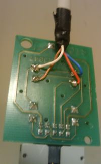
Unfortunately, the cables are cut, probably somewhere in the basement, by estimating where the signaling cable leaves; you can see the white cable going into the metal conduit on the far right side of the windowed wall. It then goes down left of the second last concrete pillar, where it disappears.
Each blind has its own transformer right behind the motor on the right side of the window, labeled as a 12v 1.3A (it's an unstabalized one), which plugs into the system as a 3.5mm jack plug (be *careful when unplugging* this, because jack plugs short momentarily)
console
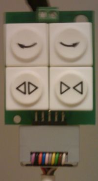
The buttons work as followed:
- ^-.- Rotate left (keep small opening but block sun)
- -.-^ Rotate completely right, closing the blinds
- <||> Rotate and open blinds/stops actions upon release
- |><| Rotate and close blinds/stops actions upon release
relay box
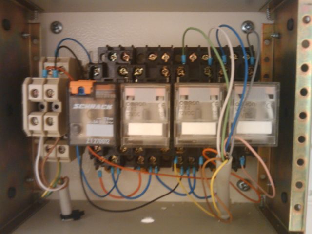
The turn left/right buttons were extended to a relay box
(come to think of it, they start rotating upon a pulse, which will eventually close them, so this setup is at least peculiar.) Stoney3K suggests this setup is a cross-linked set of 12VDC relays in a set/reset flip-flop configuration, meaning the relay will latch when you push the 'close' button, but release once power is disengaged through the motor control or end stop switch.
This unit is missing a (fairly common, 12VDC) power supply. The current rating is marked on the socketed relays.
blinds
The blinds open up from the center. Note that the string at window 4 is fubar: better not use the open function because you won't be able to close it anymore. To demount the blinds, do the following
- unplug the power supply
- unplug the jack connector and box headers
- with grace, bend the plastic sheets 45° towards you, use a fingernail to open up the clip a bit, and you'll be able to remove the sheet easily
- repetition is inevitable
- press firm on each of the two metal clips on the back of the rail, while holding that ;)
- ..
- profit!
motor unit
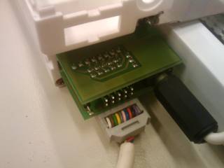
The blinds signaling system uses a daisy-chaining plug-on module (it's two double sided prints soldered on top of each other) with two 10 pins box headers (see picture).
The top connector (close to the ceiling) is used as input, while the bottom header is connected to the next set of blinds.
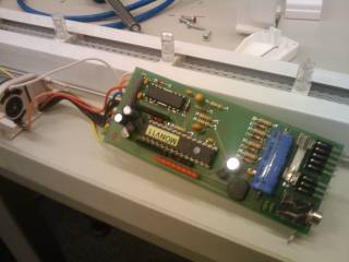
The PCB has several easy identifyable components on it, for example:
- a PIC processor (the big IC with the sticker)
- a motor driver IC (most likely H-bridge, that silly looking IC)
- a voltage rectifier, the big black thing below the shiney capacitor
- a voltage regulator LM series (not LM317 though, can't remember), the small black thing below the shiney capacitor
Also, the unit has two DC motors and 4 end-detectors (microswitches)
pinout
Warning: colors are not verified yet, but are plausible to be correct. The current colors might need swapping in pairs of two, due to the layout of the box header.
Also, timings can be off, but are reasonable guidelines.
From the relay box, the rightmost relay connecting the blue and orange wires do the 'clockwise' turning, while the second right one (using white and brown wires) do 'counter clockwise'.
All pinouts are connector side, not print side
Daisy chain pin socket (both are similar, but some pins might not be 'chained'
 2   10
.-----.
|:::::|
'-- --'
 1   9

Main controller pin socket
 2       18
.---------.
|::::: :::|
'-- ------'
 1       17

Box header (cables and remote)
 1   10
.-----.
|:::::|
'--_--'
 2   8
| pin | color | indicator | function | remark |
|---|---|---|---|---|
| 1 | white | VIN | unsure; possibly to power the driver IC | driver side: connected through the 8-pin jumper in the daisy-chain module, remote side: connected with pin 2 |
| 2 | brown | VIN | unsure; possibly to power the driver IC | driver side: connected through the 3-pin jumper in the daisy-chain module, remote side: connected with pin 1 |
| 3 | green | |> <| | rotates to 20°(CCW), closes blinds and rotates to 0° | momentary switch style actuation time: 3.5s, 6s and 2s |
| 4 | yellow | <| |> | rotates to 180°(CW), back to 160°(CCW) and opens blinds | momentary switch style actuation time: 5.5s, 1.5s and 5.5s |
| 5 | gray | ^-.- | closes and rotates CW to 160° alternatively, rotates to 20° and back to 160° |
continuous switch (until end stop switch) runs for 5.5s and 4.5s (alternatively, 7s) |
| 6 | pink | NC | Not connected | |
| 7 | blue | -.-^ | closes and rotates CCW to 0° | continuous switch (until end stop switch) runs for 5.5s and 1.5s |
| 8 | orange | VEE/GND | switch common (ground) | emittor side of the transistors to be connected |
| 9 | black | GND | unsure; possibly to power the driver IC | driver side: connected through the 3-pin jumper in the daisy-chain module, remote side: connected with pin 10 |
| 10 | purple | GND | unsure; possibly to power the driver IC | driver side: connected through the 8-pin jumper in the daisy-chain module, remote side: connected with pin 9 |
| 11 | - | NC | - | No pin |
| 12 | - | NC | - | No pin |
| 13 | - | ? | ||
| 14 | - | VCC | useful for connecting custom circuitry Note: this could also be something like busy | |
| 15 | - | GND | useful for connecting custom circuitry | |
| 16 | - | VCC | useful for connecting custom circuitry Note: this could also be something like busy | |
| 17 | - | ? | ||
| 18 | - | ? |
The two motors are regular DC motors with on each side an end switch.
I'd like to draft something up with a simple ATMEGA168 and some MOSFETs to drive the motors directly and keep the system calibrated (positionally) using the end stop switches. Using some RS422 receivers we could control the whole lot directly from any UART-capable serial device and set the blinds in any arbitrary position we want. Stoney3K 23:24, 26 November 2011 (CET)
