Difference between revisions of "LedWall"
m (removed invalid property value) |
m (set project picture) |
||
| (One intermediate revision by the same user not shown) | |||
| Line 3: | Line 3: | ||
|Members=PsychiC | |Members=PsychiC | ||
|Description=Fixing an awesome LED-Wall | |Description=Fixing an awesome LED-Wall | ||
| + | |Picture=LEDWall5.jpg | ||
}} | }} | ||
Fixing an awesome LED-Wall | Fixing an awesome LED-Wall | ||
| Line 9: | Line 10: | ||
The LED wall seems to be made by Snyder Technology Inc, and they have a standard solution to send data to these LED walls: | The LED wall seems to be made by Snyder Technology Inc, and they have a standard solution to send data to these LED walls: | ||
| − | [http://www. | + | [http://www.led-card.com/product_info.php?cPath=18&products_id=11 THIS] is a PCI card which inputs DVI video signal, and outputs the data over UTP to the LED wall. |
| − | |||
| − | |||
| − | |||
It looks like it is also possible to control it with the led studio software: | It looks like it is also possible to control it with the led studio software: | ||
Latest revision as of 16:33, 22 September 2016
| Project: LedWall | |
|---|---|
| Featured: | |
| State | Completed |
| Members | PsychiC |
| GitHub | No GitHub project defined. Add your project here. |
| Description | Fixing an awesome LED-Wall |
| Picture | |
| |
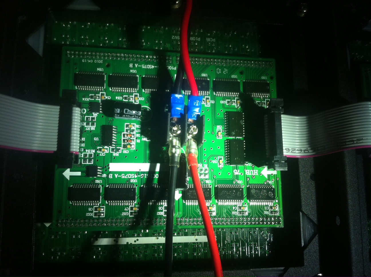
Fixing an awesome LED-Wall Details to be announced
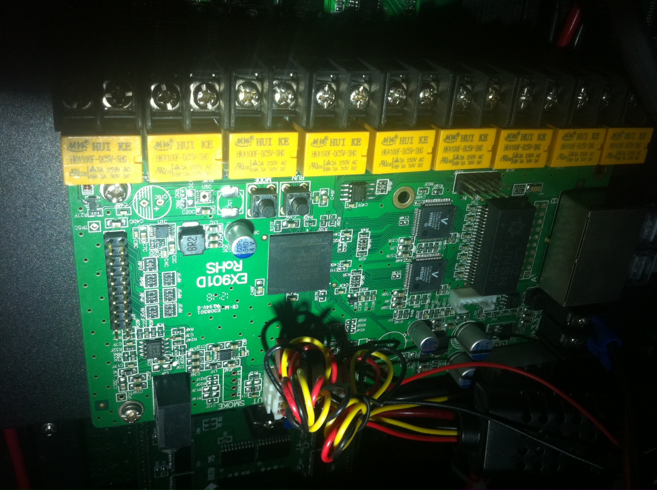
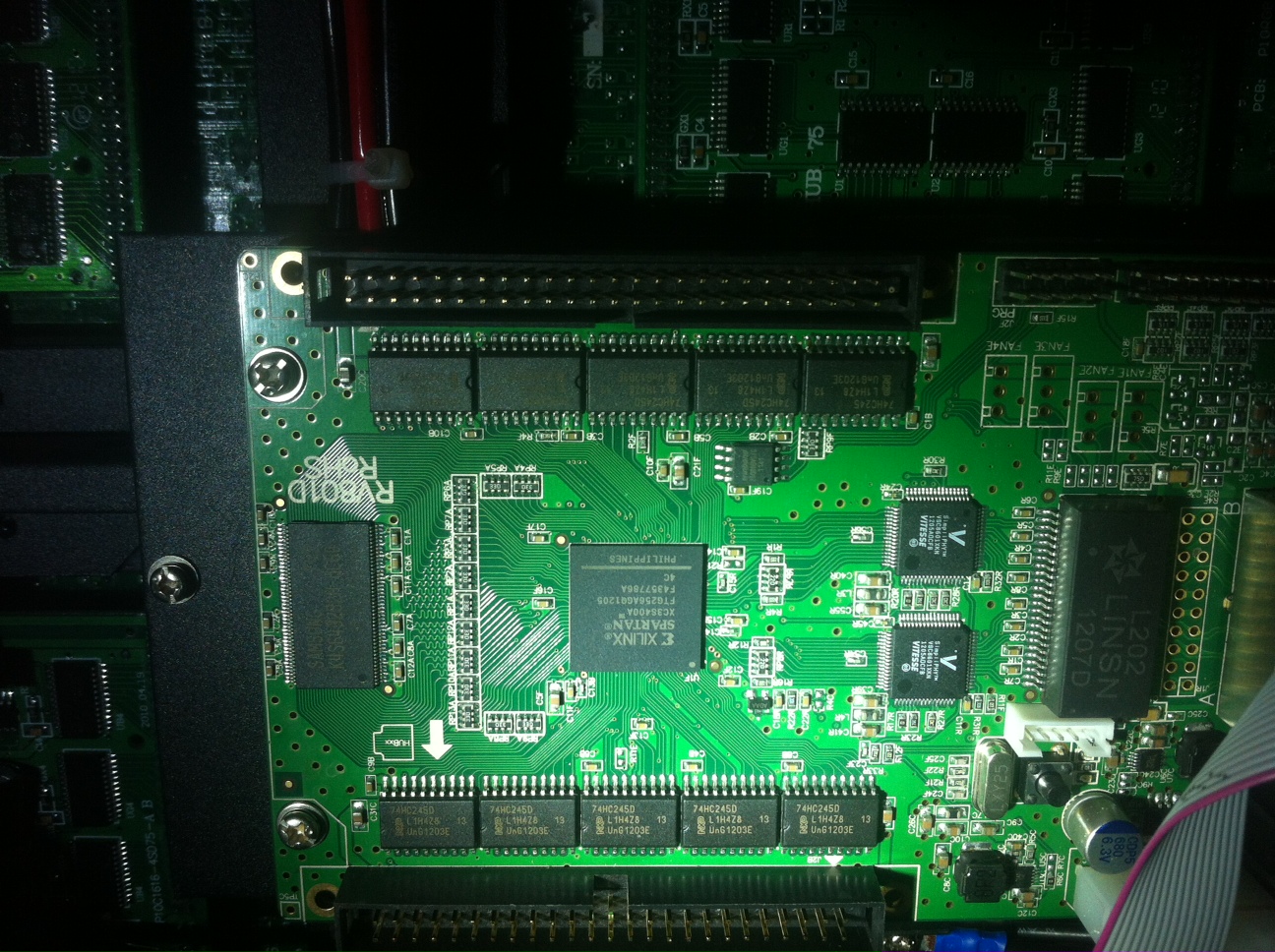
The LED wall seems to be made by Snyder Technology Inc, and they have a standard solution to send data to these LED walls:
THIS is a PCI card which inputs DVI video signal, and outputs the data over UTP to the LED wall.
It looks like it is also possible to control it with the led studio software: http://www.linsn.net/
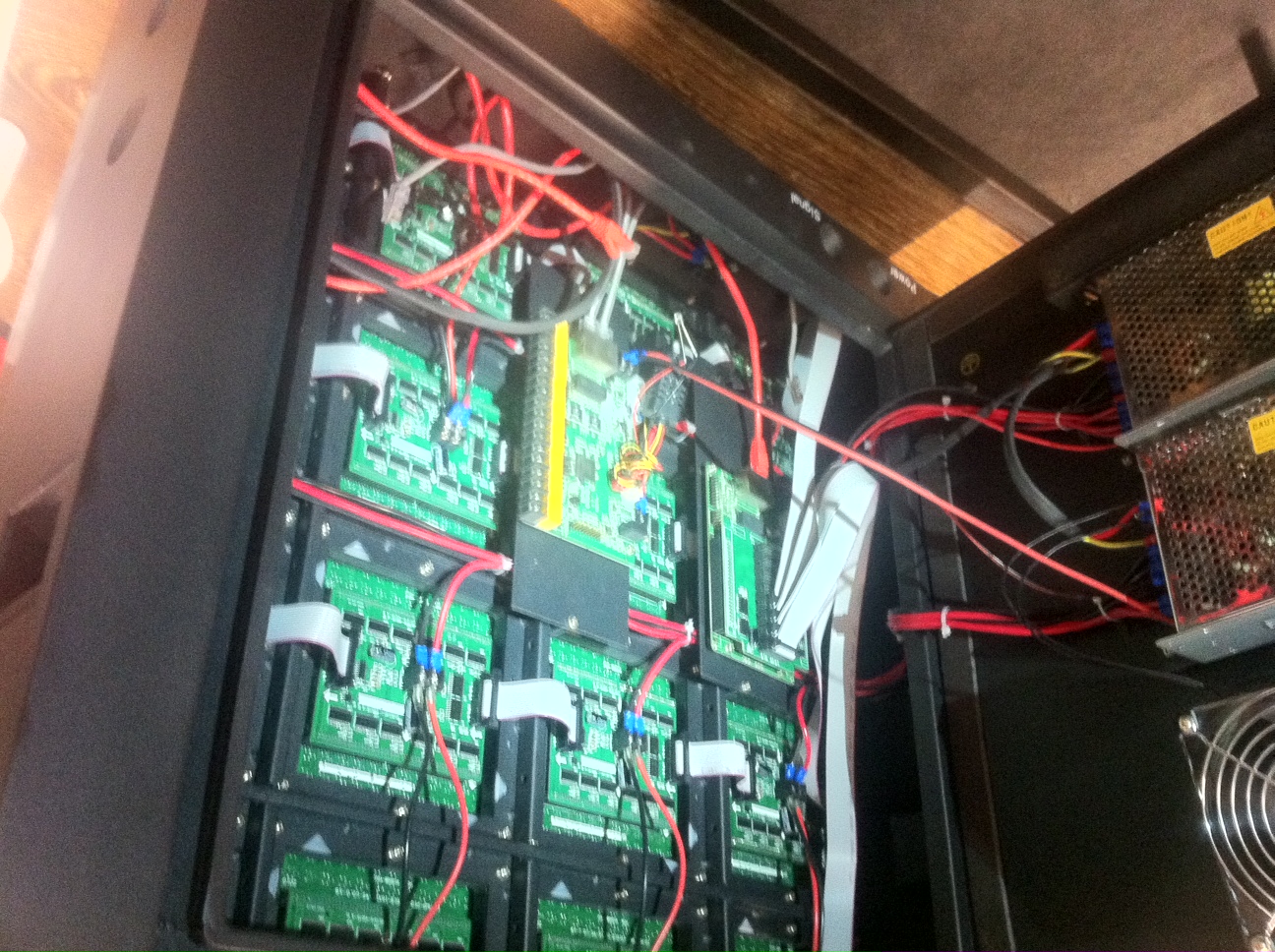
The LED wall consists of 6 segments making a 3x2 grid :
[2-1][2-2][2-3]
[1-1][1-2][1-3]
The computer node should be hookup up to segment 1-1 and has daisy chain ports for connecting the other segments. Segment 2-1 should be hookup up last.
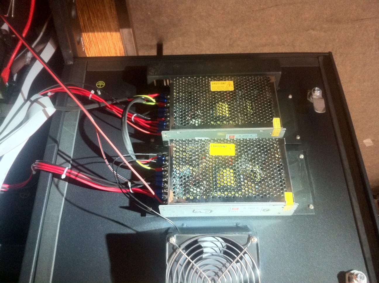
The power had no specific plugs yet and is connected using a small strip and Y-connectors on the inside. The data is connected using regular UTP and all the segments have UTP ports on the inside.
