Difference between revisions of "Mobile Spacestate Indicator"
m (updated youtube link) |
|||
| Line 165: | Line 165: | ||
[https://www.youtube.com/watch?v=T1gCaTu5Bmg&hd=1 YouTube video] | [https://www.youtube.com/watch?v=T1gCaTu5Bmg&hd=1 YouTube video] | ||
<div style="border: none; padding: 1ex; text-align:center; background: ;"> | <div style="border: none; padding: 1ex; text-align:center; background: ;"> | ||
| − | {{#widget: | + | {{#widget:YouTube|id=T1gCaTu5Bmg}} |
| − | | | ||
| − | |||
| − | |||
| − | |||
| − | }} | ||
</div> | </div> | ||
Revision as of 17:20, 8 December 2014
| Project: Mobile Spacestate Indicator | |
|---|---|
| Featured: | |
| State | Completed |
| Members | Vicarious, Da Syntax |
| GitHub | No GitHub project defined. Add your project here. |
| Description | Replace the factory car center console lights with a hackerspace state indicator |
| Picture | |
| No project picture! Fill in form Picture or Upload a jpeg here | |
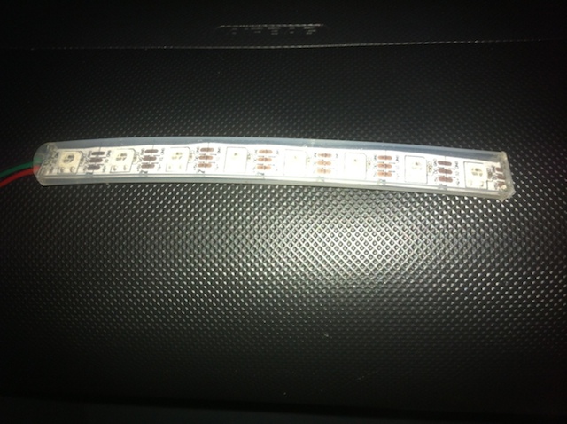
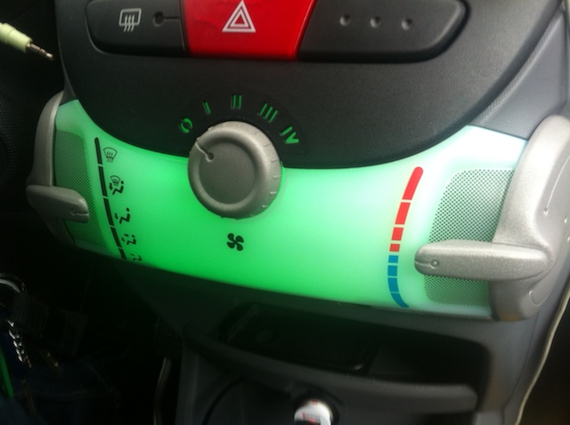
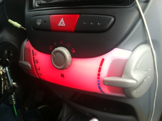
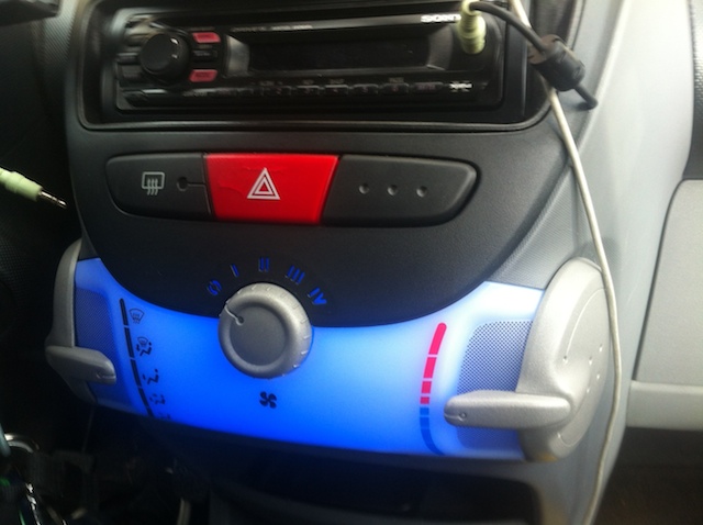
I'm the proud owner of a Citroën C1. For a while I've been wanting to replace the orange lights that are installed in my car's center console. At 30C3 I've been given a short RGB LED strip consisting of 8 individually addressable LEDs (WS2812). (Thanks Matt!) Inspired by videos on YouTube where others replaced their center console lights, I decided to create a hackerspace status indicator in my car.
Contents
Requirements
- Raspberry Pi
- Arduino Uno
- Short RGB LED strip
- 12V cigarette lighter USB adapter
- USB WiFi adapter
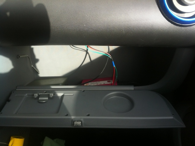
Step 1: Prepare the Raspberry Pi
- Connect a small USB WiFi adapter to your Raspberry Pi and configure wpa_gui to automatically connect to your smartphone when tethering is enabled.
- Save the following code to a file named spacestate.py
- Note: unless your favorite hackerspace is also ACKspace, you have to replace the URL with the one from your favorite hackerspace. It must point to the SpaceAPI JSON object of your hackerspace. You can find the current list at http://spaceapi.net/directory.json
#!/usr/bin/env python
# coding=utf-8
import json, serial, time, urllib2
ser = serial.Serial('/dev/ttyACM0', 9600)
URL = "https://ackspace.nl/status.php"
def get_json():
        try:
                con = urllib2.urlopen(URL)
                content = con.read()
                hs_json = json.loads(content.decode('utf8'))
                return hs_json
        except IOError:
                ser.write('b')
# print "Network error"
        except ValueError:
                ser.write('p')
# print "Malformatted json"

def print_info(hs_json):
        if hs_json['open']:
                ser.write('g')
# print "Hackerspace is open"
        else:
                ser.write('r')
# print "Hackerspace is closed"

while 1:
        jsonret = get_json()
        try:
                print_info(jsonret)
        except:
                pass
        time.sleep(30)
Original sample code is taken from [1]
- Make sure that spacestate.py is automatically started when the Raspberry Pi is booting, because we will be running the Raspberry Pi headless in the glove box. I followed the instructions on this blog article to run the python script on boot.
Step 2: Prepare the Arduino Uno
- Follow the instructions on [2] to download and install the Adafruit NeoPixel library.
- Upload the following code to control the RGB LED strip from the Arduino Uno:
#include < Adafruit_NeoPixel.h >

#define PIN 6

// Parameter 1 = number of pixels in strip
// Parameter 2 = Arduino pin number (most are valid)
// Parameter 3 = pixel type flags, add together as needed:
//   NEO_KHZ800  800 KHz bitstream (most NeoPixel products w/WS2812 LEDs)
//   NEO_KHZ400  400 KHz (classic 'v1' (not v2) FLORA pixels, WS2811 drivers)
//   NEO_GRB     Pixels are wired for GRB bitstream (most NeoPixel products)
//   NEO_RGB     Pixels are wired for RGB bitstream (v1 FLORA pixels, not v2)
Adafruit_NeoPixel strip = Adafruit_NeoPixel(8, PIN, NEO_GRB + NEO_KHZ400);

// IMPORTANT: To reduce NeoPixel burnout risk, add 1000 uF capacitor across
// pixel power leads, add 300 - 500 Ohm resistor on first pixel's data input
// and minimize distance between Arduino and first pixel.  Avoid connecting
// on a live circuit...if you must, connect GND first.

void setup() {
  strip.begin();
  strip.show(); // Initialize all pixels to 'off'
  Serial.begin(9600);
}


void loop() {
  if (Serial.available() > 0)
  {
    char incoming = Serial.read();
    if (incoming == 'g')
    {
      setColor(0, 255, 0); //green
    }
    else if(incoming == 'r')
    {
      setColor(255, 0, 0); //red
    }
    else if(incoming == 'b')
    {
      setColor(0, 0, 255); //blue
    }
    else if(incoming == 'p')
    {
      setColor(255, 0, 255); //purple
    }
    Serial.print(incoming);
  }
}

void setColor(int r, int g, int b)
{
  for(int i = 0; i < 8; i++)
  {
    strip.setPixelColor(i, r, g, b);
    strip.show();
  }
}
Original code is taken from [3]
Step 3: Soldering
The RGB LED strip has 3 connections: +5V, DI and GND. Because the short LED strip only has 8 LEDs, it can be powered from the Arduino Uno's 5V directly.
- Find three wires that are long enough to reach the center console from the glovebox, through the dashboard.
- Solder three wires to the three connections on the RGB LED strip: +5V, DI and GND.
Warnings taken from http://learn.adafruit.com/adafruit-neopixel-uberguide/arduino-library
Adding a ~470 ohm resistor between your microcontroller's data pin and the data input on the NeoPixels can help prevent spikes on the data line that can damage your first pixel. Please add one between your micro and NeoPixels! We also recommend adding a large capacitor (1000 µF, 6.3V or higher) across the + and – terminals. This prevents the initial onrush of current from damaging the pixels.
Can NeoPixels be powered directly from the Arduino’s 5V pin?
Sometimes. The Arduino can continuously supply only about 500 milliamps to the 5V pin. Each NeoPixel can draw up to 60 milliamps at full brightness. So yes, you can skip the separate DC supply and power directly off the Arduino as long as just a few pixels are used, or more if the colors and overall brightness are low. When in doubt, give the pixels a separate power supply.
- Solder header pins to the other side of the three wires so they will stay plugged in to the Arduino.
Step 4: Installation
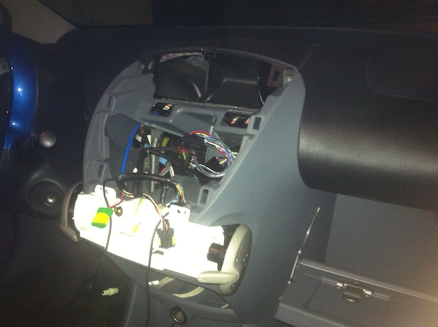
- Open the center console with tools and patience.
- Remove the original two small orange light bulbs. Store them somewhere safe in case you want to sell your car in it's original state.
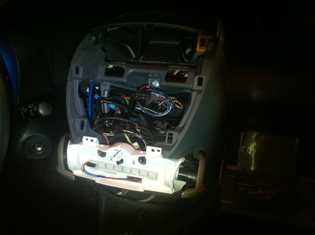
- Pull the three wires from the center console to the glove box.
- Attach the RGB LED strip to the white plastic case with the LEDs pointed towards the white plastic case, otherwise you'll see each individual LED through the translucent center console. I used wide clear tape to attach the RGB LED strip.
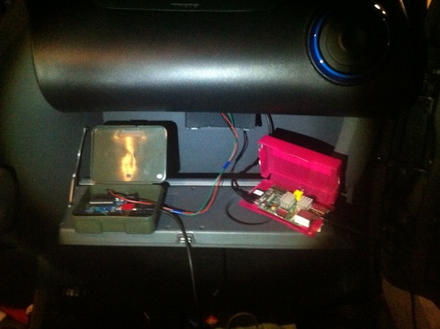
- Pull a micro USB cable from the glove box through the hole below the 12V cigarette lighter socket under the center console.
- Attach the USB cable to a 12V cigarette lighter plug - USB adapter. Attach the micro USB to the Raspberry Pi.
- The Arduino will be powered and controlled from the Raspberry Pi, so connect the Arduino Uno to the Raspberry Pi using an USB A-B cable.
- Attach the three wires from the RGB LED strip to the Arduino Uno. (+5V, pin 6, GND).
- Close the center console and the glove box.
- Start your car, after a while the Raspberry Pi will be booted and the spacestate.py will be running in the background as daemon process.
- Keep your eyes on the road while driving, don’t get distracted by your shiny mobile hackerspace space state indicator!
Pics or it didn't happen!
Video with two added animations.. a rainbow pattern and knight rider animation: YouTube video
