Difference between revisions of "Coinvox 22"
(keypad and display update) |
(added snippets of information everywhere. added image. small typo fixes) |
||
| Line 4: | Line 4: | ||
|Description=Get an old payphone to work again | |Description=Get an old payphone to work again | ||
}} | }} | ||
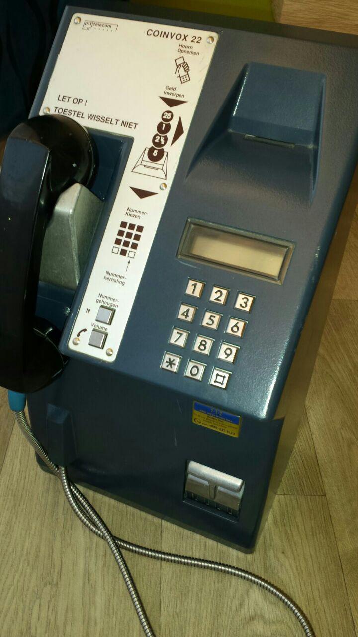
| − | [[Image:Coinvox 22 front.jpg|thumb|185px]][[Image:Coinvox 22 inside.jpg|thumb|185px]] | + | [[Image:Coinvox 22 front.jpg|thumb|185px|Coinvox 22 looks complete..]] |
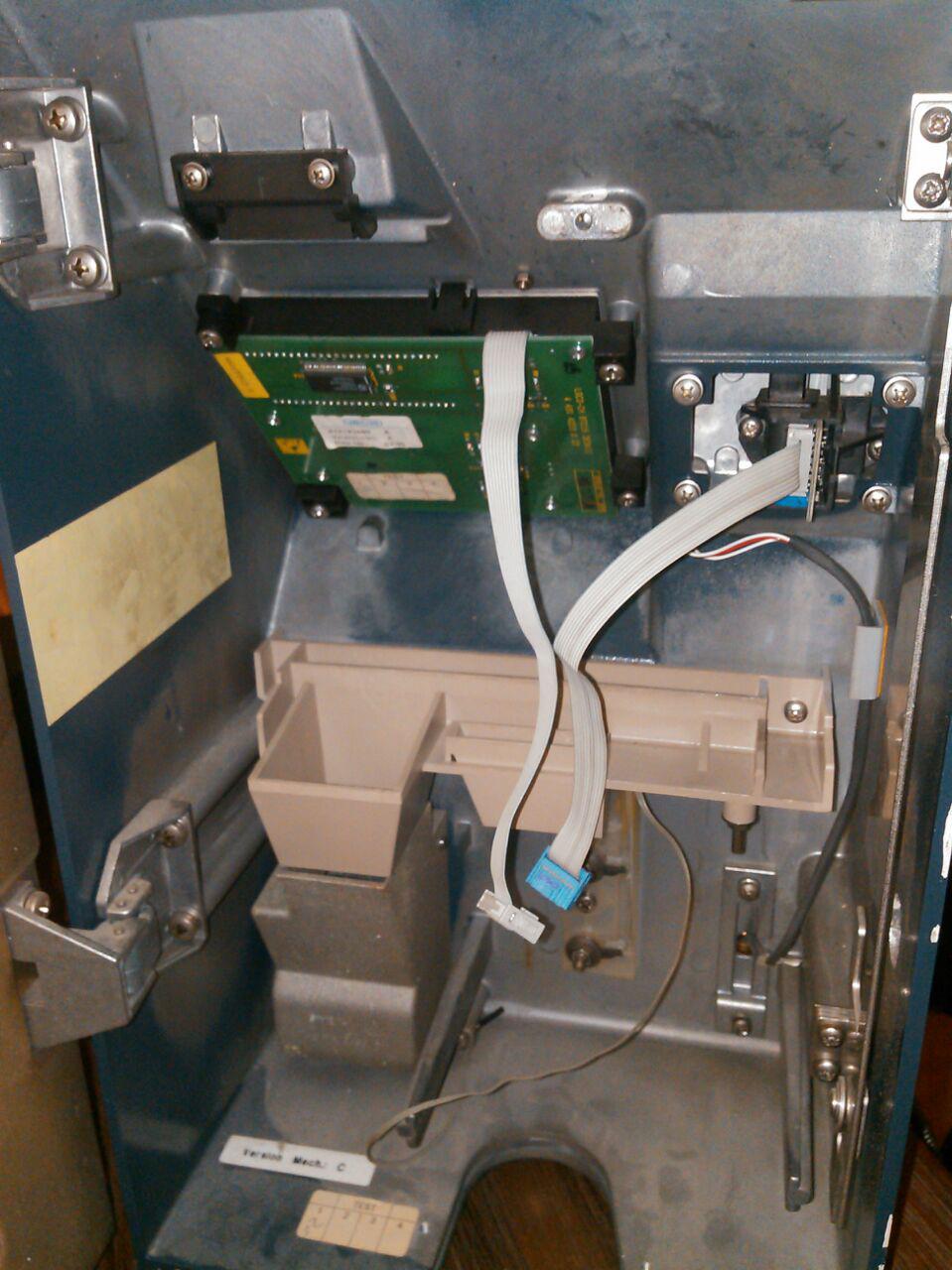
| + | [[Image:Coinvox 22 inside.jpg|thumb|185px|..but is stipped empty :(]] | ||
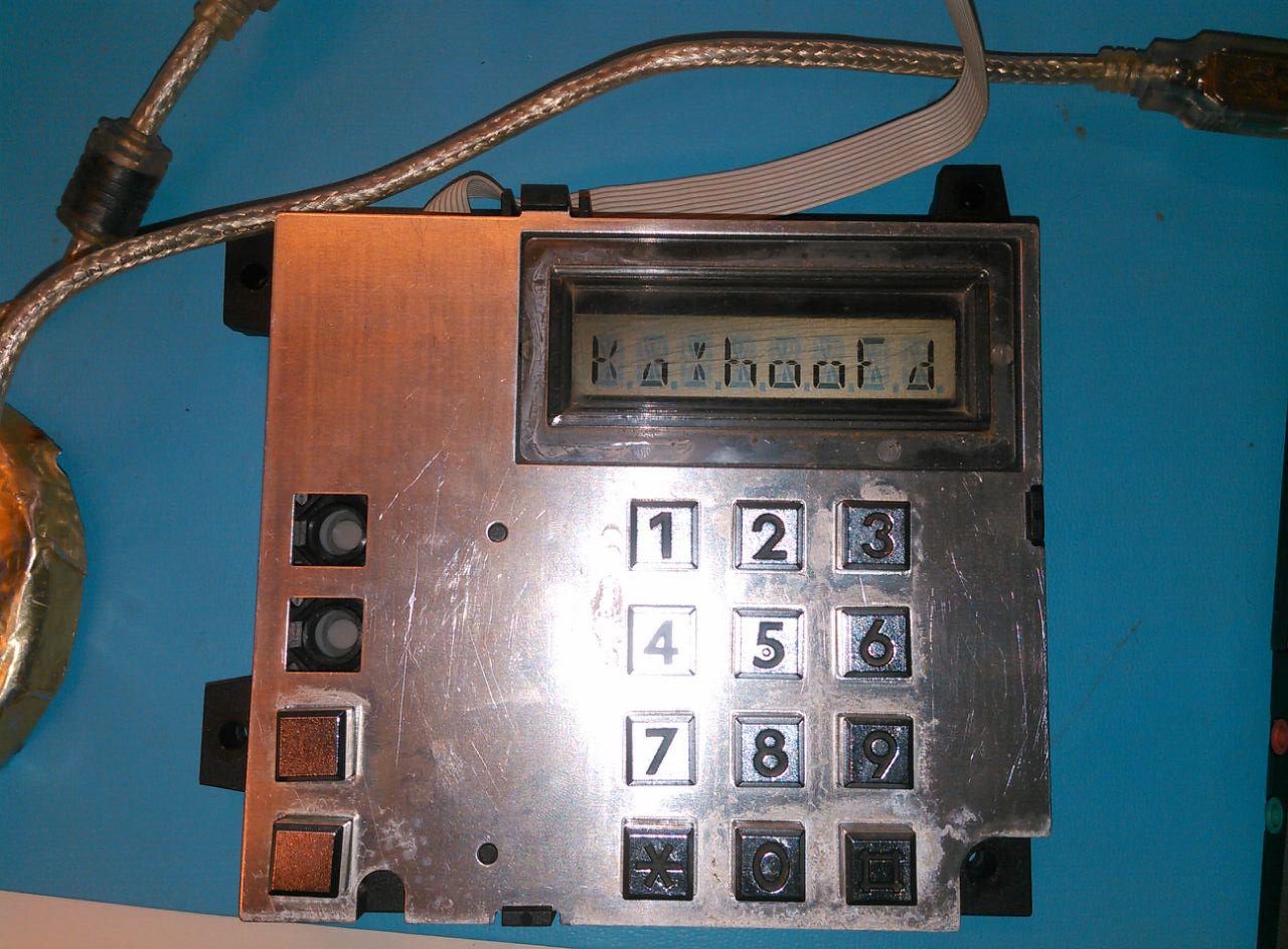
| + | [[Image:Coinvox 22 keypad.jpg|thumb|185px|Keypad I<sup>2</sup>C interfaced]] | ||
== synopsis == | == synopsis == | ||
I got myself a Coinvox 22, reasonably cheap. | I got myself a Coinvox 22, reasonably cheap. | ||
| − | The downside is: the inner workings have been stripped out, so it's just a metal box with keypad and display, a handset with | + | The downside is: the inner workings have been stripped out, so it's just a metal box with keypad and display, a handset with hook-switch and a small transformer. |
No coin mech, no ringer, no phone. | No coin mech, no ringer, no phone. | ||
== inside == | == inside == | ||
| − | === handset / | + | === handset / hook-switch === |
| − | * 2 | + | The handset is tested and is in good shape. It is connected to a PCB. |
| + | * 2 different reed switches | ||
* 4 coils | * 4 coils | ||
| − | * 2 3-pin SOT 23 ( | + | * 2 3-pin SOT 23 (SMD) diodes(?) (D1, D2: A7 P 45) |
'''J1''' | '''J1''' | ||
| + | Handset connector. Layout is (male) PCB connector side. | ||
|o spk | |o spk | ||
|o| mic - | |o| mic - | ||
| Line 24: | Line 28: | ||
'''J2''' | '''J2''' | ||
| + | Connector which ought to go into the main PCB. Layout is (female) connector side. | ||
mic+ 2 |oo| 1 spk | mic+ 2 |oo| 1 spk | ||
spk 4 |oo| 3 mic- | spk 4 |oo| 3 mic- | ||
| Line 30: | Line 35: | ||
P2 10|oo| 9 NO2 | P2 10|oo| 9 NO2 | ||
| − | Note: SW1 switches first (about 2mm) when hanging up | + | Note: SW1 switches first (about 2mm) when hanging up, probably used for muting the microphone. |
=== keypad / display === | === keypad / display === | ||
| Line 38: | Line 43: | ||
'''J''' | '''J''' | ||
| + | Display/keypad connector. Layout is (female) connector side. Int needs pullup, and print is found working at 5V. | ||
SCL 2 |oo| 1 SDA | SCL 2 |oo| 1 SDA | ||
4 |oo| 3 | 4 |oo| 3 | ||
| Line 45: | Line 51: | ||
'''Display''' | '''Display''' | ||
| − | * 8 × 14 segment display, | + | * 8 × 14 segment display, characters are filled from the right |
* 52 pins with the only the outer 9 connected (36) | * 52 pins with the only the outer 9 connected (36) | ||
| − | * uses 4 | + | * uses 4 back-plane mode (all corners) |
| − | Segment layout | + | Segment layout. Note that bit 3 is not used, which aligns the characters to 16 bit. |
<pre> | <pre> | ||
15 | 15 | ||
| − | + | _________ | |
| \11 | / | | | \11 | / | | ||
| Line 63: | Line 69: | ||
__________ | __________ | ||
0 o12 | 0 o12 | ||
| − | + | bit 3: not used | |
</pre> | </pre> | ||
| Line 102: | Line 108: | ||
To read out the keypad (on interrupt pullup), set one row low and read the column nibble. Repeat for each row. Low bit means key pressed. | To read out the keypad (on interrupt pullup), set one row low and read the column nibble. Repeat for each row. Low bit means key pressed. | ||
| − | + | Text on the PCB: | |
:LGCO-CH BTC15 DESKII | :LGCO-CH BTC15 DESKII | ||
:4 431 4223 0 22 | :4 431 4223 0 22 | ||
| − | + | Text found on some stickers: | |
:Landis & GYR | :Landis & GYR | ||
:412197580 A | :412197580 A | ||
:Version.mec: A | :Version.mec: A | ||
| − | Date fab : 02/95 | + | :Date fab : 02/95 |
== plans == | == plans == | ||
| Line 119: | Line 125: | ||
== todo == | == todo == | ||
| − | * identify ICs, obtain datasheet, determine pinouts | + | * upload display/keypad initialization commands |
| + | * write a library for the display/keypad (fix the hacky code) | ||
| + | * see if the serial protocol of a Cisco phone is of any use | ||
| + | * find an old mechanical phone bell | ||
| + | * <s>identify ICs, obtain datasheet, determine pinouts</s> Success! | ||
Revision as of 12:35, 26 October 2015
| Project: Coinvox 22 | |
|---|---|
| Featured: | |
| State | Active |
| Members | xopr |
| GitHub | No GitHub project defined. Add your project here. |
| Description | Get an old payphone to work again |
| Picture | |
| No project picture! Fill in form Picture or Upload a jpeg here | |
synopsis
I got myself a Coinvox 22, reasonably cheap. The downside is: the inner workings have been stripped out, so it's just a metal box with keypad and display, a handset with hook-switch and a small transformer.
No coin mech, no ringer, no phone.
inside
handset / hook-switch
The handset is tested and is in good shape. It is connected to a PCB.
- 2 different reed switches
- 4 coils
- 2 3-pin SOT 23 (SMD) diodes(?) (D1, D2: A7 P 45)
J1 Handset connector. Layout is (male) PCB connector side.
|o  spk
|o| mic -
|o| mic +
|o  spk
J2 Connector which ought to go into the main PCB. Layout is (female) connector side.
mic+ 2 |oo| 1 spk
 spk 4 |oo| 3 mic-
 NC1 6 |oo |5 n/c
 NO1 8 |oo| 7 P1
  P2 10|oo| 9 NO2
Note: SW1 switches first (about 2mm) when hanging up, probably used for muting the microphone.
keypad / display
- IC2: PCF8576T (Universal LCD driver for low multiplex rates, I2C address 38h)
- IC3: PCF8574T (Remote 8-bit I/O expander for I2C-bus with interrupt)
- Addresses tied to ground; address 20h.
J Display/keypad connector. Layout is (female) connector side. Int needs pullup, and print is found working at 5V.
SCL 2 |oo| 1 SDA
    4 |oo| 3
GND 6 |oo |5 VCC
    8 |oo| 7
Int 10|oo| 9
Display
- 8 × 14 segment display, characters are filled from the right
- 52 pins with the only the outer 9 connected (36)
- uses 4 back-plane mode (all corners)
Segment layout. Note that bit 3 is not used, which aligns the characters to 16 bit.
       15
    _________

  | \11 |   / |
 2|  \  |7 /6 |14
  |   \ | /   |
 10----  -----5
  |   / | \   |
 1|  /  |  \4 |13
  | /9  |8  \ |
   __________
        0       o12
 bit 3: not used
Keypad
| col1 (P7) | col2 (P4) | col3 (P5) | col4 (P6) | |
|---|---|---|---|---|
| row1 (P1) | n/c | 1 | 2 | 3 |
| row2 (P1) | n/c | 4 | 5 | 6 |
| row3 (P2) | N | 7 | 8 | 9 |
| row4 (P3) | Vol | * | 0 | # |
To read out the keypad (on interrupt pullup), set one row low and read the column nibble. Repeat for each row. Low bit means key pressed.
Text on the PCB:
- LGCO-CH BTC15 DESKII
- 4 431 4223 0 22
Text found on some stickers:
- Landis & GYR
- 412197580 A
- Version.mec: A
- Date fab : 02/95
plans
- upload reference material of the Coinvox phones (hacktic, 't klaphek, telephone museums ([1][2][3][4][5][6][7])
- experiment with my (front fed) coin mech (or look for a top fed mech that fits)
- experiment with a cisco phone (see if I can use the softkeys and the AUX port to read quarters or just Euro coins
- connect an ATA to an old phone
todo
- upload display/keypad initialization commands
- write a library for the display/keypad (fix the hacky code)
- see if the serial protocol of a Cisco phone is of any use
- find an old mechanical phone bell
identify ICs, obtain datasheet, determine pinoutsSuccess!


