Difference between revisions of "ESP-2"
(moved most of the information to ESP8266 so removing it here) |
(restored original author of the ESP Egg Salad Programmer) |
||
| Line 1: | Line 1: | ||
<noinclude>{{Featured}}</noinclude>{{Project | <noinclude>{{Featured}}</noinclude>{{Project | ||
| − | |State= | + | |State=Completed |
| − | |Members=Prodigity | + | |Members=Prodigity |
|Description=Playing around with cheap wifi modules | |Description=Playing around with cheap wifi modules | ||
}}== synopsis == | }}== synopsis == | ||
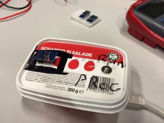
| − | To make the ESP8266 more accessible to everyone | + | To make the ESP8266 more accessible to everyone [[User:Prodigity|Prodigity]] has created a "programmer" which allows for easy firmware uploading and communication with the module. |
[[Image:Runprogrun.JPG|335px|thumb|Behold, the ESP^2 (esp egg salad programmer).]] | [[Image:Runprogrun.JPG|335px|thumb|Behold, the ESP^2 (esp egg salad programmer).]] | ||
Revision as of 10:35, 24 July 2015
Featured article
ESP-2 had been flagged as a featured article and will automatically appear on the Main Page.
| Project: ESP-2 | |
|---|---|
| Featured: | |
| State | Completed |
| Members | Prodigity |
| GitHub | No GitHub project defined. Add your project here. |
| Description | Playing around with cheap wifi modules |
| Picture | |
| No project picture! Fill in form Picture or Upload a jpeg here | |
synopsis
To make the ESP8266 more accessible to everyone Prodigity has created a "programmer" which allows for easy firmware uploading and communication with the module.
Revision 1.1
xopr Modified the ESP^2 a bit:
- Added three wires (VCC, GND and GPIO2) for Dallas temperature sensor debugging (wire ends are insulated)
- Added pullup resistor was added so GPIO0 can be used after the device has been booted
- Added resistor to the 5V ESP^2 TX signal (should be two diodes I guess, the resistor divider didn't work)
Todo
Find a way to program the ESP-12 (2mm pitch) modules without much hassle (note that it needs a 10k resistor between GPIO15 and GND) to boot correctly
