Automatic window blinds
| Project: Automatic window blinds | |
|---|---|
| Featured: | |
| State | Active |
| Members | [[Members::User:xopr|xopr]] |
| GitHub | No GitHub project defined. Add your project here. |
| Description | Connect and interface the existing window blinds |
| Picture | |
| No project picture! Fill in form Picture or Upload a jpeg here | |
Contents
disclaimer
Before starting to tear things apart, make note that the hire contract states that we are not allowed to make changes (i.e. structural) to the building. Therefore we need to inform the building manager what needs to be done to fix the blinds, first. Contact one of the board members, or Xopr before grabbing the soldering iron ;)
The contract also states that small technical maintenance must be performed by the tenants themselves. Large technical problems must be reported to the front desk. Fixing the window blinds, is this considered small or large technical maintenance? I'll ask Camelot :) - Vicarious 08:44, 10 March 2011 (CET)
intro
The space has 8 windows with a width of a little less than 1.80m per window, each with a motorized window blind mechanism. This is an opportunity to automate this system to our needs.
Last time, eracoon and CoolePascal were helping out, so they deserve credits here (correct me if I'm wrong :)
the project
The stuff works more or less. Now it's time to optimize/automate.
Some ideas to work out:
- Control it with Arduino+Ethernet Shield or MyEthernet
- Put on the letters ACKspace
- Make the blinds individually controllable
- your creativity here
Describe your plans on the discussion tab, so we can execute them here
specs
Unfortunately, the cables are cut, probably somewhere in the basement, by estimating where the signaling cable leaves; you can see the white cable going into the metal conduit on the far right side of the windowed wall. It then goes down left of the second last concrete pillar, where it disappears.
Each blind has its own transformer right behind the motor on the right side of the window, labeled as a 12v 1.3A (it's an unstabalized one), which plugs into the system as a 3.5mm jack plug (be *careful when unplugging* this, because jack plugs short momentarily)
console
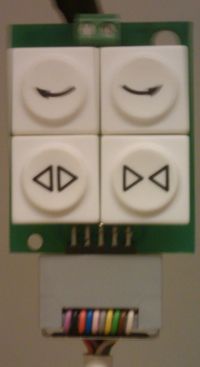
The buttons work as followed:
- ^-.- Rotate completely left
- -.-^ Rotate completely right
- <||> Rotate and open blinds/stops actions upon release
- |><| Rotate and close blinds/stops actions upon release
relay box
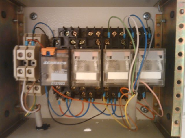 The turn left/right buttons were extended to a relay box (come to think of it, they start rotating upon a pulse, which will eventually close them, so this setup is at least peculiar.
This unit is missing a power supply.
blinds
The blinds open up from the center. Note that the string at window 4 is fubar: better not use the open function because you won't be able to close it anymore. To demount the blinds, do the following
- unplug the power supply
- unplug the jack connector and box headers
- with grace, bend the plastic sheets 45° towards you, use a fingernail to open up the clip a bit, and you'll be able to remove the sheet easily
- repetition is inevitable
- press firm on each of the two metal clips on the back of the rail, while holding that ;)
- ..
- profit!
motor unit
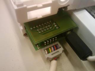
The blinds signaling system uses a daisy-chaining plug-on module (it's two double sided prints soldered on top of each other) with two 10 pins box headers (see picture).
The top connector (close to the ceiling) is used as input, while the bottom header is connected to the next set of blinds.
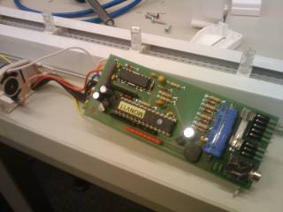
The PCB has several easy identifyable components on it, for example:
- a PIC processor (the big IC with the sticker)
- a motor driver IC (most likely H-bridge, that silly looking IC)
- a voltage rectifier, the big black thing below the shiney capacitor
- a voltage regulator LM series (not LM317 though, can't remember), the small black thing below the shiney capacitor
Also, the unit has two DC motors and 4 end-detectors (microswitches)
pinout
Warning: colors/pins are not verified yet, but can easily be derived from the switch panel. The current colors might need swapping in pairs of two, due to the layout of the box header.
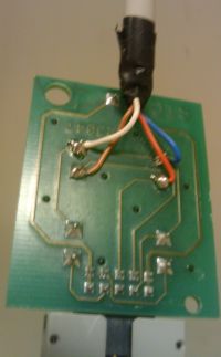
From the relay box, the rightmost relay connecting the blue and orange wires do the 'clockwise' turning, while the second right one (using white and brown wires) do 'counter clockwise'.
Following the connections on the button console PCB, you can derive that pins 1+2 (purple and black) and 9+10 (brown and white) suggest power supply (not sure if it is in- or output),
Assuming that pin 1 (purple), is the bottom left pin, this should mean that:
- (purple) power A (ground?)
- (black) power A
- (orange) switch common
- (blue) Rotate CCW -.-^
- pink) NC
- (gray) Rotate CW ^-.-
- (yellow) open |><|
- (green) close <||>
- (brown) power B (VCC?)
- (white) power B
