Arbitrary Sampling Rate Converter in VHDL
| Project: Arbitrary Sampling Rate Converter in VHDL | |
|---|---|
| Featured: | |
| State | Completed |
| Members | Danny Witberg |
| GitHub | No GitHub project defined. Add your project here. |
| Description | ASRC's: What, how, why? |
| Picture | |
| No project picture! Fill in form Picture or Upload a jpeg here | |
Contents
- 1 Summary
- 2 Hardware solutions
- 3 Theory of operation
- 4 The wrong way of upsampling: Copy samples
- 5 The wrong way of upsampling: Linear interpolation
- 6 The right way of upsampling: Sinc function
- 7 Filters: FIR filter
- 8 Filters: IIR filter
- 9 Serializing an IIR filter
- 10 Block schematic of the ASRC
- 11 Actual results
- 12 VHDL code
Summary
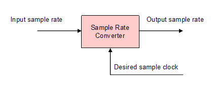
This project describes the theory of an Arbitrary Sampling Rate Converter, and a practical lightweight implementation in VHDL. ASRC's are often used in digital audio, to adapt an input to an output which differ in sampling rates to each other. If sampling rates are not matched, clicking noises and distortion can be heard and it could ruin your audio signal.
Hardware solutions
Standalone hardware SRC IC's for converting digital audio exist, but they are not cheap. To name some:
- Analog Devices AD1895, AD1896 and AD1893
- Cirrus Logic CS8420, CS8421, and CS8422
- Texas Instruments SRC4190, SRC4382, SRC4392, SRC4190, SRC4184, SRC4194, SRC4190, SRC4192 and SRC4193
- AKM AK4120, AK4121, AK4122, AK4127, AK4128 and AK4129
Theory of operation
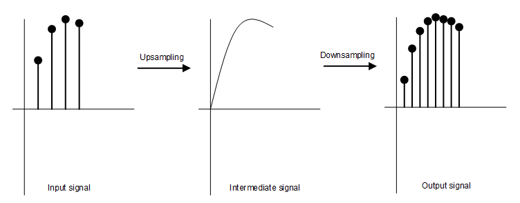
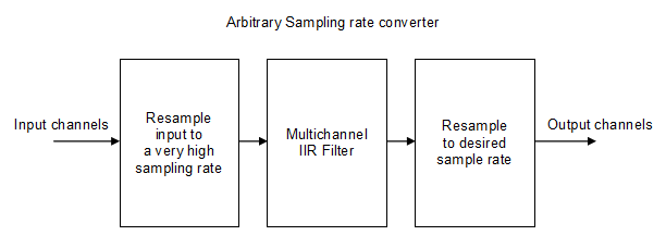
Conversion between sampling rates of a digital (audio) signal is all about interpolation. Between the actual input signal and the desired output signal, additional samples must be created, or omitted. There are a number of techniques that can be used for this, but the most effective is to convert or "upsample" the input signal to a very high sampling rate, and then resample that signal to the desired output sampling rate. There are several ways to upsample a signal:
- Copy input samples
- Linear interpolation
- Sinc function interpolation
The wrong way of upsampling: Copy samples
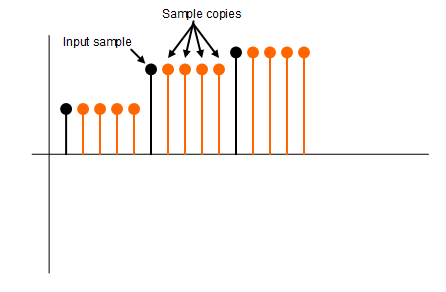
If you want a higher sampling rate, the easiest way to do this is to resample the input signal at a higher rate, thus creating copies of input samples. However, is is not the way to properly do this, because the interpolated samples do not differ from the actual input samples, and thus not improving any clicking noise and distortion. The output signal will sound just as bad, if not worse, than no conversion at all. Some other manipulation of the signal must be applied to improve quality.
The wrong way of upsampling: Linear interpolation
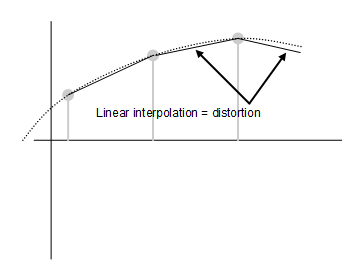
With a linear interpolation, you look at two consecutive input samples. Take the number of intermediate samples you want between these two, and gradually change the output value from one to the next sample. Although this can easily be implemented, this is not a good way to interpolate. This is because the original signal is very unlikely to change in a linear fashion, and if you interpolate like this, you introduce a distortion into the output signal. It is better than the copy sample method, but not usable for digital audio.
The right way of upsampling: Sinc function
A sinc function with the function of a low pass filter is the right way to go for digital audio applications. You start off with the least desirable option of upsampling: copy original samples into the new signal. This creates a frequency of 0 between those copied samples, because the signal does not change basically. But when a new original sample presents itself, a very high frequency is introduced, because the output value suddenly changes into the value of the original sample. This very high frequency is much higher than the maximum frequency of the original signal. If we filter out this very high frequency, the output signal rids itself from that sudden change in value, therefore must change slowly over time. This is exactly what we need! There are several ways to implement a low pass filter, but they can generally be divided into two categories: a Finite Impulse Response (FIR) filter and an Infinite Impulse Response (IIR) filter.
Filters: FIR filter
The way a FIR filter works is to multiply a input signal with another filter signal. The shape of the filter signal is called the filter kernel, and it determines the response of the FIR filter. You can have kernels for a low pass, high pass, band pass , band stop, or any other response you desire. How easy is it to load up a FIR filter function with a low pass filter kernel, and off we go! But unfortunately, there are some downsides to the FIR filter that we really can not use in our application. Because the whole kernel must be applied to the input signal, you'll need much computational power. If your filter kernel is 64 samples in length, which in fact is not that long, you'll need 64 multiplications to get just one output sample. If you want to process several channels, the speed that you require would rise even more. Another downside are memory requirements. All intermediate values of the output signal would have to be stored in memory while all of the kernel is applied. You would need the length of the kernel, times the amount of channels, of storage memory. On top of that, consider the output delay of the FIR filter. Only once the whole filter kernel is applied to an input sample, you will know what the outcome is. A delay of the length of the filter kernel is introduced in your signal, and depending of the length of the kernel, this can be very noticable in a live application.
Filters: IIR filter
With an IIR filter, an output sample not only depends on the input, but also output samples are taken into account. IIR filters have none of the downsides that FIR filters have. Kernels are short, therefore quickly applied, output delay is basically one sample, and required memory is also much less. Ideal right? Sure, but there are things to consider. If your output signal depends on other output samples, there is a very real chance of your filter function to run out of control. The gain of your filter function can never exceed unity, or else your filter works as an oscillator! This is why the coefficients of the IIR filter are chosen very carefully. Also the response of the filter may be not that clean compared to a FIR. But if the IIR is well designed, it can be a very good low pass filter which we require.
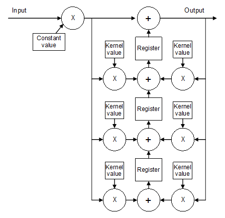
Math at work! This is an actual example of a IIR filter, with a 2kHz low pass kernel. Notice how the fast changes (e.g. the high frequencies) are filtered out in the data output, while the lower frequencies are all still present.
Serializing an IIR filter
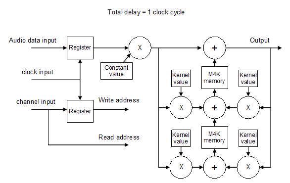
Having this IIR filter is of course great, but what if we have to filter more than one channel? Can we input several channels at once? Not without modification. The registers that store intermediate values have to be changed for memory blocks so they can store the values for more than one channel. These M4K blocks inside an Altera Cyclone can hold 4096 bits. With a 32 bit audio word width, this comes down to 128 addresses. This is the maximum amount of channels we can hold in a single M4K block, more channels and we have to combine several memory blocks for one filter tap. Because it takes one clock cycle for the memory to read the stored value, some additional delays have to be inserted in the data and address lines in order for the filter to work properly. In all, we end up with a block schematic like so:
Block schematic of the ASRC
Actual results
This is a first example of a real world sampling rate conversion. The upper signal is the input to the sampling rate converter. Notice the jagged edges of the signal. Through the IIR filter, these sudden changes in the signal are smoothed out, and the lower signal is the output of the IIR filter, sampled at approximately 1MHz. This result is with the same low pass coördinates as the previous 1/24th sampling rate filter, so at 1MHz this comes down to about 41kHz. With a more carefully chosen IIR filter, better results can be achieved.
VHDL code
library ieee;
use ieee.std_logic_1164.all;
use ieee.std_logic_arith.all;
use ieee.std_logic_signed.all;

entity iir_filter_tap is
 generic(
  coeff_x : integer := 1;
  coeff_y : real := 1.0000000000
 );
 port(
  clock : in std_logic;
  wr_address : in std_logic_vector(6 downto 0);
  rd_address : in std_logic_vector(6 downto 0);
  input_x : in std_logic_vector(31 downto 0);
  input_y : in std_logic_vector(31 downto 0);
  input_z : in std_logic_vector(31 downto 0);
  output_z : out std_logic_vector(31 downto 0)
 );
end entity iir_filter_tap;

architecture behavioural of iir_filter_tap is

 component mult32x32 is
  port(
   dataa : in std_logic_vector(31 downto 0);
   datab : in std_logic_vector(31 downto 0);
   result : out std_logic_vector(31 downto 0)
  );
 end component mult32x32;

 component mem32 is
  port(
   clock : in std_logic;
   data : in std_logic_vector(31 downto 0);
   rdaddress : in std_logic_vector(6 downto 0);
   wraddress : in std_logic_vector(6 downto 0);
   wren : in std_logic;
   q : out std_logic_vector(31 downto 0)
  );
 end component mem32;

 signal coeff_y_value : std_logic_vector(31 downto 0);
 signal output_added : std_logic_vector(31 downto 0);
 signal input_x_multiplied : std_logic_vector(31 downto 0);
 signal input_y_multiplied : std_logic_vector(31 downto 0);

begin

 generate_y0_multiplier_p: if coeff_y <= real(1) and coeff_y > real(0) generate
  coeff_y_value <= conv_std_logic_vector(integer(coeff_y * real(2147483648)),32);
  y_multiplier : mult32x32
  port map(
   dataa => input_y(31) & input_y(29 downto 0) & '0',
   datab => coeff_y_value,
   result => input_y_multiplied
  );
 end generate generate_y0_multiplier_p;
 generate_y0_multiplier_n: if coeff_y <= real(0) and coeff_y > real(-1) generate
  coeff_y_value <= not conv_std_logic_vector(integer(coeff_y * real(2147483648)),32);
  y_multiplier : mult32x32
  port map(
   dataa => input_y(31) & input_y(29 downto 0) & '0',
   datab => coeff_y_value,
   result => input_y_multiplied
  );
 end generate generate_y0_multiplier_n;
 generate_y1_multiplier_n: if coeff_y <= real(-1) and coeff_y > real(-2) generate
  coeff_y_value <= not conv_std_logic_vector(integer(coeff_y * real(1073741824)),32);
  y_multiplier : mult32x32
  port map(
   dataa => input_y(31) & input_y(28 downto 0) & "00",
   datab => coeff_y_value,
   result => input_y_multiplied
  );
 end generate generate_y1_multiplier_n;
  generate_y1_multiplier_p: if coeff_y <= real(2) and coeff_y > real(1) generate
  coeff_y_value <= conv_std_logic_vector(integer(coeff_y * real(1073741824)),32);
  y_multiplier : mult32x32
  port map(
   dataa => input_y(31) & input_y(28 downto 0) & "00",
   datab => coeff_y_value,
   result => input_y_multiplied
  );
 end generate generate_y1_multiplier_p;

 generate_x0_multiplier: if coeff_x = 0 generate
  input_x_multiplied <= (others => '0');
 end generate generate_x0_multiplier;
 generate_x1_multiplier: if coeff_x = 1 generate
  input_x_multiplied <= input_x(31) & input_x(31) & input_x(31) & input_x(31) & input_x(31 downto 4);
 end generate generate_x1_multiplier;
 generate_x2_multiplier: if coeff_x = 2 generate
  input_x_multiplied <= input_x(31) & input_x(31) & input_x(31) & (input_x(31 downto 3));
 end generate generate_x2_multiplier;
 generate_x3_multiplier: if coeff_x = 3 generate
  input_x_multiplied <= (input_x(31) & input_x(31) & input_x(31) & (input_x(31 downto 3))) + (input_x(31) & input_x(31) & input_x(31) & input_x(31) & input_x(31 downto 4));
 end generate generate_x3_multiplier;
 generate_x4_multiplier: if coeff_x = 4 generate
  input_x_multiplied <= input_x(31) & input_x(31) & (input_x(31 downto 2));
 end generate generate_x4_multiplier;
 generate_x5_multiplier: if coeff_x = 5 generate
  input_x_multiplied <= (input_x(31) & input_x(31) & (input_x(31 downto 2))) + (input_x(31) & input_x(31) & input_x(31) & input_x(31) & input_x(31 downto 4));
 end generate generate_x5_multiplier;
 generate_x6_multiplier: if coeff_x = 6 generate
   input_x_multiplied <= (input_x(31) & input_x(31) & (input_x(31 downto 2))) + (input_x(31) & input_x(31) & input_x(31) & (input_x(31 downto 3)));
 end generate generate_x6_multiplier;

 output_added <= input_y_multiplied + input_x_multiplied + input_z;

 multichannel_register: mem32
 port map(
  clock => clock,
  data => output_added,
  rdaddress => rd_address,
  wraddress => wr_address,
  wren => '1',
  q => output_z
 );

end behavioural;

library ieee;
use ieee.std_logic_1164.all;
use ieee.std_logic_arith.all;
use ieee.std_logic_signed.all;

entity iir_filter is
 port(
  clock : in std_logic;
  address : in std_logic_vector(6 downto 0);
  data_input : in std_logic_vector(23 downto 0);
  data_output : out std_logic_vector(23 downto 0)
 );
end entity iir_filter;

architecture behavioral of iir_filter is

 component mult32x32 is
  port(
   dataa : in std_logic_vector(31 downto 0);
   datab : in std_logic_vector(31 downto 0);
   result : out std_logic_vector(31 downto 0)
  );
 end component mult32x32;

 component iir_filter_tap is
  generic(
   coeff_x : integer;
   coeff_y : real
  );
  port(
   clock : in std_logic;
   wr_address : in std_logic_vector(6 downto 0);
   rd_address : in std_logic_vector(6 downto 0);
   input_x : in std_logic_vector(31 downto 0);
   input_y : in std_logic_vector(31 downto 0);
   input_z : in std_logic_vector(31 downto 0);
   output_z : out std_logic_vector(31 downto 0)
  );
 end component iir_filter_tap;

 signal delay_address : std_logic_vector(6 downto 0);
 signal delay_input : std_logic_vector(23 downto 0);
 signal inter_output : std_logic_vector(31 downto 0);
 signal inter_input : std_logic_vector(31 downto 0);
 signal inter_tap0 : std_logic_vector(31 downto 0);
 signal inter_tap1 : std_logic_vector(31 downto 0);

begin

 inter_output <= inter_input + inter_tap0;
 data_output <= inter_output(31) & inter_output(26 downto 4);

k_multiplier : mult32x32
 port map(
  dataa => delay_input(23) & delay_input(23) & delay_input(23) & delay_input(23) & delay_input & "0000",
  datab => conv_std_logic_vector(123707428,32),
  result => inter_input
 );

delay : process (clock)
begin
 if clock'event and clock = '1' then
  delay_address <= address;
  delay_input <= data_input;
 end if;
end process delay;

iir_tap_0 : iir_filter_tap
 generic map(
  coeff_x => 2,
  coeff_y => 1.6329931619
 )
 port map(
  clock => clock,
  wr_address => delay_address,
  rd_address => address,
  input_x => inter_input,
  input_y => inter_output,
  input_z => inter_tap1,
  output_z => inter_tap0
 );

iir_tap_1 : iir_filter_tap
 generic map(
  coeff_x => 1,
  coeff_y => -0.6905989232
 )
 port map(
  clock => clock,
  wr_address => delay_address,
  rd_address => address,
  input_x => inter_input,
  input_y => inter_output,
  input_z => (others => '0'),
  output_z => inter_tap1
 );

end behavioral;
