Coinvox 22
| Project: Coinvox 22 | |
|---|---|
| Featured: | No |
| State | Stalled |
| Members | xopr |
| GitHub | coinvox |
| Description | Get an old payphone to work again |
| Picture | |

| |
Contents
synopsis
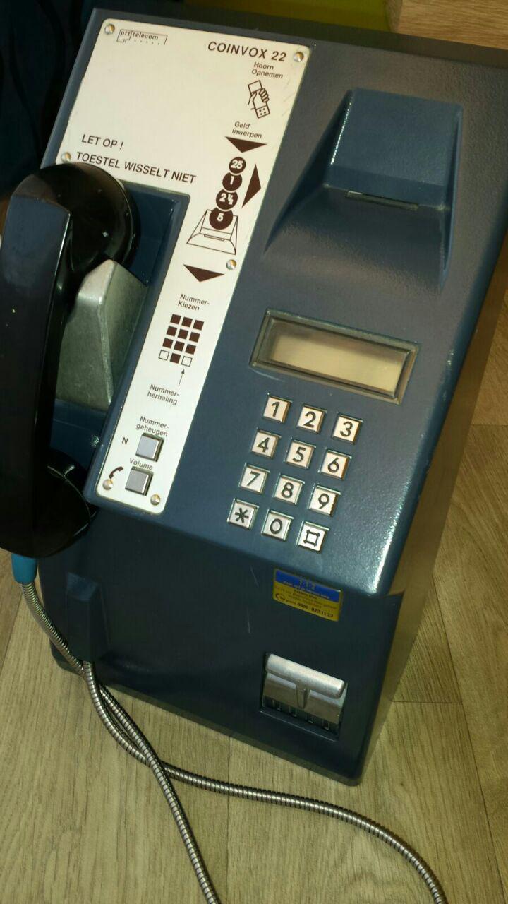
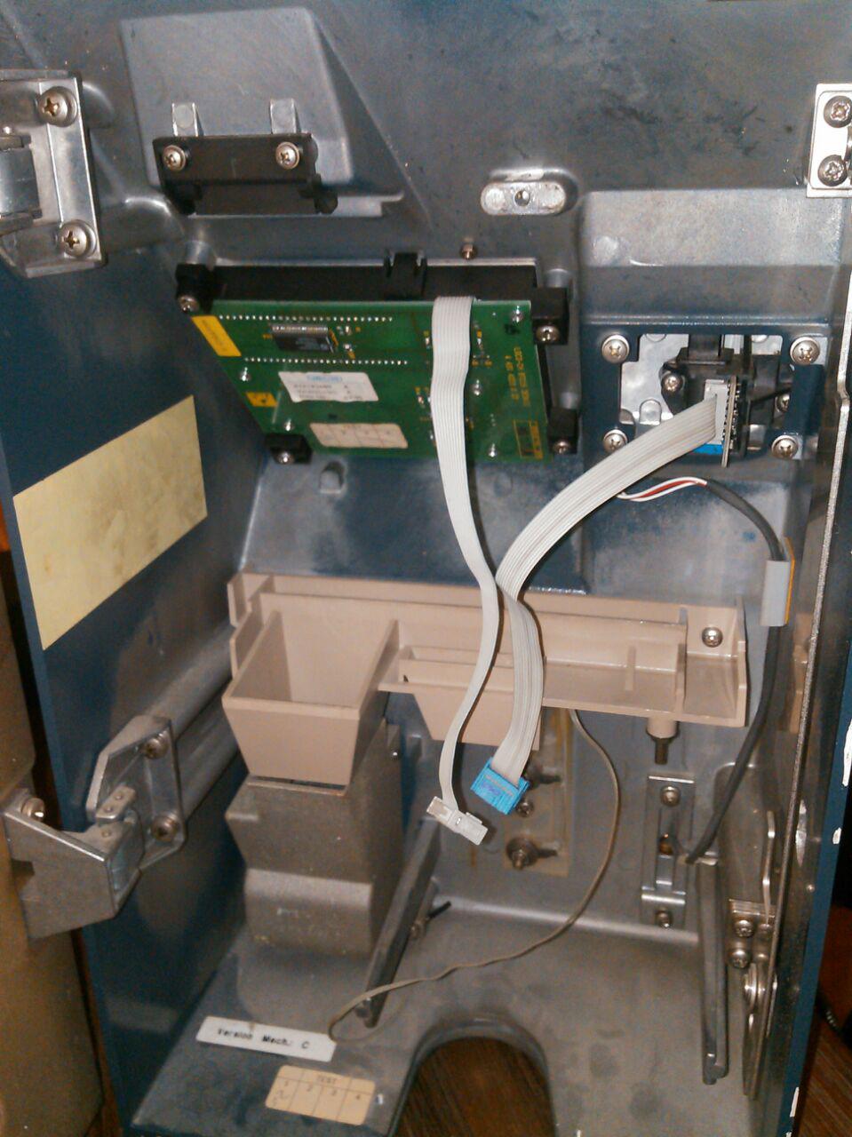
I got myself a Coinvox 22, reasonably cheap. The downside is: the inner workings have been stripped out, so it's just a metal box with keypad and display, a handset with hook-switch and a small transformer.
No coin mech, no ringer, no phone.
update
Got contacted by Jaytaph who was working on it as well. He wrote a snippet that actually looks better than the hacky code I (xopr) wrote last october.
inside
handset / hook-switch
The handset is tested and is in good shape. It is connected to a PCB.
- 2 different reed switches
- 4 coils
- 2 3-pin SOT 23 (SMD) diodes(?) (D1, D2: A7 P 45)
J1 Handset connector. Layout is (male) PCB connector side.
|o  spk
|o| mic -
|o| mic +
|o  spk
J2 Connector which ought to go into the main PCB. Layout is (female) connector side.
mic+ 2 |oo| 1 spk
 spk 4 |oo| 3 mic-
 NC1 6 |oo |5 n/c
 NO1 8 |oo| 7 P1
  P2 10|oo| 9 NO2
Note: SW1 switches first (about 2mm) when hanging up, probably used for muting the microphone.
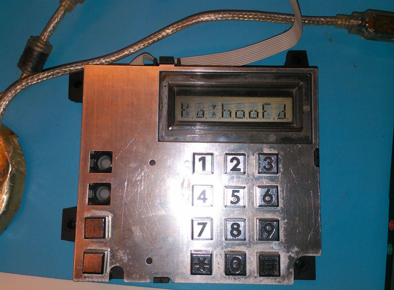
keypad / display
- IC2: PCF8576T (Universal LCD driver for low multiplex rates, I2C address 38h)
- IC3: PCF8574T (Remote 8-bit I/O expander for I2C-bus with interrupt)
- Addresses tied to ground; address 20h.
J Display/keypad connector. Layout is (female) connector side. Int needs pullup, and print is found working at 5V.
SCL 2 |oo| 1 SDA
    4 |oo| 3
GND 6 |oo |5 VCC
    8 |oo| 7
Int 10|oo| 9
Display
- 8 × 14 segment display, characters are filled from the right
- 52 pins with the only the outer 9 connected (36)
- uses 4 back-plane mode (all corners)
Segment layout. Note that bit 3 is not used, which aligns the characters to 16 bit.
       15
    _________

  | \11 |   / |
 2|  \  |7 /6 |14
  |   \ | /   |
 10----  -----5
  |   / | \   |
 1|  /  |  \4 |13
  | /9  |8  \ |
   __________
        0       o12
 bit 3: not used
Keypad
| col1 (P7) | col2 (P4) | col3 (P5) | col4 (P6) | |
|---|---|---|---|---|
| row1 (P0) | n/c | 1 | 2 | 3 |
| row2 (P1) | n/c | 4 | 5 | 6 |
| row3 (P2) | N | 7 | 8 | 9 |
| row4 (P3) | Vol | * | 0 | # |
To read out the keypad (on interrupt pullup), set one row low and read the column nibble. Repeat for each row. Low bit means key pressed. Theoretically, 1178 key combinations (up to 4 simultaneous keys) can be detected. Key ghosting occurs when pressing keys in the shape of an L (including the 'corner' key), and can be detected if more than one row and more than one column is low when scanning individual lines.
Text on the PCB:
- LGCO-CH BTC15 DESKII
- 4 431 4223 0 22
Text found on some stickers:
- Landis & GYR
- 412197580 A
- Version.mec: A
- Date fab : 02/95
keypad ghosting
Since the keypad is a simple matrix, pressing multiple keys can introduce key ghosting (getting positive result on a key that isn't pressed).
A simple explanation: If '1', '2' and '4' are pressed together, and the rows are scanned by setting each column low for a moment, row 0 and 1 will be pulled low in both the iteration of column 0 and 1 being low. Column 1 low brings a special scenario: row 0 is pulled low by pressing '2' and therefore column 0 will be pulled low as well by the pressing of '1'. By having '4' pressed and column 0 low, row 1 will also be pulled low, which in the case of the iteration of column 1, '5' will be marked as pressed which it isn't.
Here is a javascript snippet (can be run in a browser's console) that determines the allowed key combination before ghosting occurs. Estimated is that 'corners' in key combination trigger ghosting:
// See keypad as 4x4 = 16 bit matrix
var allowedKeys = [];
for ( var keys = 1; keys < (1<<16); keys++ )
{
	var flaggedBits  = 0b0000;
	var excludedBits = 0b0000;
	var ghosting = false;

	// Disallow 2 keys since they are missing on the designated phone keypad
	if ( keys & 0b1000100000000000 )
		ghosting = true;

	for ( var nibbleIdx = 0; nibbleIdx < 4; nibbleIdx++ )
	{
		var nibble = (keys >>> (nibbleIdx * 4)) & 0xf;

		// Current nibble & exclude overlap: ghosting
		if ( nibble & excludedBits )
		{
			ghosting  = true;
			continue;
		}

		if ( nibble === 0b0001 || nibble === 0b0010 || nibble === 0b0100 || nibble === 0b1000 )
		{
			// Single bit: flag
			flaggedBits |= nibble;
		}
		else
		{
			// Multi bit: exclude
			excludedBits |= nibble;
		}

		// Flag bits already processed
		//flaggedBits |= nibble;

		if ( ghosting )
			continue;
	}

	// flag & exclude overlap: ghosting
	if ( flaggedBits & excludedBits )
		ghosting  = true;

	// No ghosting? Add this combination
	if ( !ghosting )
		allowedKeys.push( keys );
}

// Show amount of allowed keys and its 'int' value
console.log( allowedKeys.length, allowedKeys )
allowedKeys.forEach( function( _k )
{
	// display a keypad matrix of pressed keys '*' for all 821 allowed combinations
	for ( var nibbleIdx = 0; nibbleIdx < 4; nibbleIdx++ )
	{
		var nibble = ((_k >>> (nibbleIdx * 4)) & 0xf).toString( 2 );
		nibble = ("000" + nibble).substr( -4 ).replace( /0/g, " " ).replace( /1/g, "*" );
		console.log( nibbleIdx, nibble );
	}
	console.log( "---" );
} );
plans
- upload reference material of the Coinvox phones (hacktic, 't klaphek, telephone museums ([1][2][3][4][5][6][7])
- experiment with my (front fed) coin mech (or look for a top fed mech that fits)
- experiment with a cisco phone (see if I can use the softkeys and the AUX port to read quarters or just Euro coins
- connect an ATA to an old phone
todo
- upload display/keypad initialization commands
- write a library for the display/keypad (fix the hacky code)
- see if the serial protocol of a Cisco phone is of any use
- find an old mechanical phone bell
identify ICs, obtain datasheet, determine pinoutsSuccess!
Location: at xopr's

