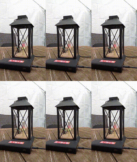
Micro sleeve
| Project: Micro sleeve | |
|---|---|
| Featured: | No |
| State | Completed |
| Members | Xopr |
| GitHub | No GitHub project defined. Add your project here. |
| Description | ART-net controlled cylindrical-ish μdisplay, it's so cute! |
| Picture | |

| |
Contents
synopsis
Inspired by the famous LED sleeve, I bought a lantern and found a tiny ledstrip on ALiExpress.
parts
The list you need to build one:
- Lantern: found a solar candle lantern at Action for roughly €5,-
- 1M 160LED/M × 2.7mm WS2812B (2020SMD) strip (12V)
- >56mm 5/8" 16mm electrical pipe (6-7cm)
- heat shrink ~56mm × 22mm 8-9cm
- ESP-12 or an ESP8266 that exposes
GPIO2 - step-down/buck converter to 3.3v
- USB-C PD trigger to 12V
- 2 × 10k resistors
- two pieces of ~10cm × 10cm scrap plywood for the pipe base
- hot glue
- 16mm drill
- some thin wire to connect all boards
- soldering equipment
- mounting hardware (or just hot glue)
- optional: 4 × 10cm × 20cm plexiglass, since the lantern came with super thin real glass, that broke once it fell
build
- flash the ESP with WLED firmware; this has all you need!
- dismantle the candle, charger and solar panel in the used lantern; it will leave a big hole at the bottom
- remove some ridges to make it flat for the plywood
- optional: replace the glass with plexiglass
- drill a hole in the center of the top plywood so it fits the electrical pipe
- wrap the LEDstrip clockwise starting from the end of the strip at the top; you will notice it will need 8,5 LEDs to make a single spiral circle and therefore second layer almost alternates with the first one
- cover it with heat shrink, ~1cm past the soldered wires at the bottom, leaving ~1cm above the pipe
- while heat shrinking, push in the top heat shrink so 'falling' water can't creep in from the top
- feed the separate connector through one of the holes out of the bottom;
- solder both the connector wire and extra wires for the buck converter to the PD-trigger board
- solder wires from the buck converter to the ESP (make sure the necessary ESP pull resistors are also present);
- include the data pin:
GPIO2 - place both plywood boards (1 inside, one from the bottom)
- place and plug in the micro sleeve
- hot glue everything to the base and make a notch for the cable to come out
notes
This will become a 19mm × 52.5mm sleeve with 8 × 20 LEDs so it will not be fully compatible with the LED sleeve Art-Net codebase (7 × 21).
Also, don't forget to pull up PD_EN and pull down GPIO15