Guerrilla VoIP
| Project: Guerrilla VoIP | |
|---|---|
| Featured: | No |
| State | Active |
| Members | xopr |
| GitHub | No GitHub project defined. Add your project here. |
| Description | low cost communication node |
| Picture | |

| |
synopsis
Try to:
- connect anything that can carry a voice channel, or, preferably, a data channel
- feed from any (cheap/renewable) energy source
- make it weather resistant and transportable
- consider standards
implementation
connect anything that can carry a voice/data channel
- copper/fibre/WiFi network
- DECT/POTS/GSM telephony
- SIP/SCCP
- HAM radio (or preferrably, CB radio: 27MC/PMR)
- copper/WiFi/USB uplink
feed from any energy source
cheap/renewable:
- solar power support
- this is the easiest renewable energy source: panels are affordable and the sun is more ore less abundant.
- battery backup support preferred
- a sealed lead acid (SLA) battery is affordable, easy to come by, easy to charge and maintenance free. Their downside is bulkiness and weight. 12V 7Ah is a good ratio between weight and energy.
weather resistant and transportable
Make sure the electronics are encased in a sturdy, weatherproof housing. It should also be easily transportable and affordable.
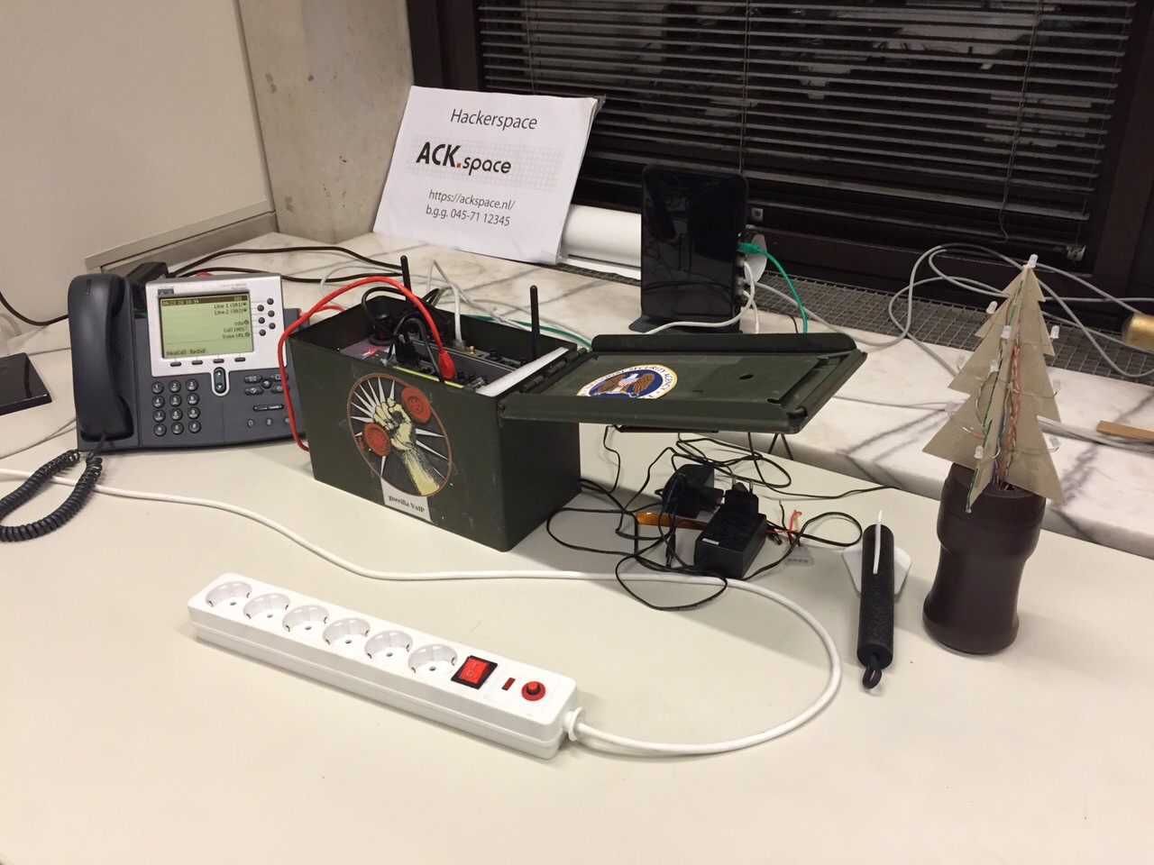
The best thing that will apply is an ammo case from an army surplus shop.
consider standards
electrically
- mains input: 100-250V~ 50-60Hz
- internal voltage rails:
- 5V: standard for raspberry pi and some network devices
- 12V: battery 'standard' and standard for other network devices
- 48V: Power over Ethernet and telephony standard
connectors
- MC4 connectors: solar
- Anderson powerpole plug: UPS
- cigarette lighter plug (ANSI/SAE J563): cars
- powerlet plug (ISO 4165): alternative/old cars and motorcycles
- double banana plug (19mm/0.75" spacing): equipment standard
current version
The current version has:
- ammo box
- 7Ah SLA battery
- banana/screw terminal
- weatherproof ethernet outlet
- 12-volt cigarette lighter receptacle
- 3D printed insert
- fuse box
- switches for device targeting power and power state preview
- Netgear GS110TP (8xPoE + 2xSFP)
- a couple Telephone system:Cisco PoE hack cable, but the switch supports pre-standard PoE
- electronics:
- 1 on-off-on momentarily 3-pole double throw: battery/external/outlet input and voltage rail status
- 3 on-off-on switch 1-pole double throw: source-destination rail (application/charge)
- 6 fuses (1, 1, 4, 4, 7.5, 7.5) for 5V rail, 10-15V rail, 48V rail, outlet, battery, ext. power
- 3 LEDs 2v 20mA
- 6 resistors (4x600R, 225R, 150R)
- 2 10W resistors (2R, 20R)
- 2 schottky diodes 4-10A
- 2 DC-DC converters (5V 3A, 48V 1.25A)
- 3 crowbar circuits (5V, 15V, 48V)
todo
- upload models and schematics
- 3D print inlay for Switch/PI holder
- install fuses and crowbar circuit
- install state leds
- install step-down converter 12->5V
- install step-up converter 12v->48V
- Raspberry PI or Orange PI
- NL dialplan (FS/Cisco)
prototyping
USB PD (USB-C)
It is possible to power the PoE switch with two USB-C powerbank for off-the-grid usage, ideal for a hackers on a bike tour. All you need is:
- 2 USB-C powerbanks that supports 20V (like the Xiaomi Mi Powerbank 3, sometimes as low as €35,- each)
- ideally, pass-through/UPS USB-C power banks like the Zmi PowerPack No. 20 Model QB826G would be best, but they're 4 times as expensive
- 2 USB-C to USB-C cables
- 2 ZY12PDN USB-C Fast Charge Trigger Poll Detector, set to 20V, connected in series (around €5,- each)
- a barrel jack 5.5x2.5mm to power the switch
See the PCB in this picture to get an idea.
Note that since the banks are connected in series, one shield/ground is lifted 20 volts; don't let any USB ground touch the other powerbank's ground in any way (also goes for the USB-A ports in this set-up; it will fail spectacularly)!
hardware
connectivity/infra
| HW | price range | voltage | power consumption | copper/Gbit | PoE | fibre | VLAN | 2.4GHz | 5GHz | DSL | ISDN | POTS | DECT | USB |
|---|---|---|---|---|---|---|---|---|---|---|---|---|---|---|
| Fritz!Box 7270 | € 50-213 | 5.5-15v | 4.3W - 5.3W | 4/0 | ? | ✓ | ✓ | ✓ | ✓ | 2×FXS / 1×FXO | 5 (6?)hs | 1×2.0 | ||
| GL-Inet | €22-30 | 5v | 1W | 2/0 | ✓ | ✓ | 1×2.0 | |||||||
| TP WR-703n | €17-25 | 5v | 1W | 1/0 | ✓ | ✓ | 1×2.0 | |||||||
| Netgear GS110TP | €126-140 (€99.64) | 48v | 4W | 8/8 | 8 | 2 | ✓ | |||||||
| TP Link TL-SG108PE | €65 | 48v | 5.2w | 8/8 | 4 | ✓ | ||||||||
| Siemens Gigaset N510 IP PRO | £53.94 (€65.39) | 6.5v | 1.2-1.3W | 1/? | ✓ | ✓ | 6hs,4sc |
hard phones / ATAs
| HW | price range | voltage | power consumption | copper/Gbit | PoE | VLAN | SIP | lines | extensible | tested on FreeSWITCH |
|---|---|---|---|---|---|---|---|---|---|---|
| Cisco 7905 | € 10-50 | 48v | 1/0 | ✓ | ✓ | 1(?) | ✓ | |||
| Cisco 7910 | 48v | 1/0 | ✓ | ✓ | 6(?) | ✓ | ||||
| Cisco 7940/7960 | € 10-50 | 48v | 5W | 2/0 | ✓ | ✓ | ✓ | 2/6 | ✓ | ✓ |
| Cisco 7941/7961 | 48v | 2/2(?) | ✓ | ✓ | ✓(?) | 2/6 | ✓ | |||
| Avaya 4620SW | 48v | 2/0? | ✓ | ✓(?) | ✓(?) | ? | ✓ | |||
| Linksys PAP2T | 5v | 10W | 1/0 | ✓ | ✓ | 2×FXS | ✓ | |||
| Sipura SPA3000 | 5v | 7.5W | 1/0 | ✓ | ✓ | 1×FXS 1×FXO | ✓ |
some power tests
hardware
| hardware | power source | U | I | Papproximated |
|---|---|---|---|---|
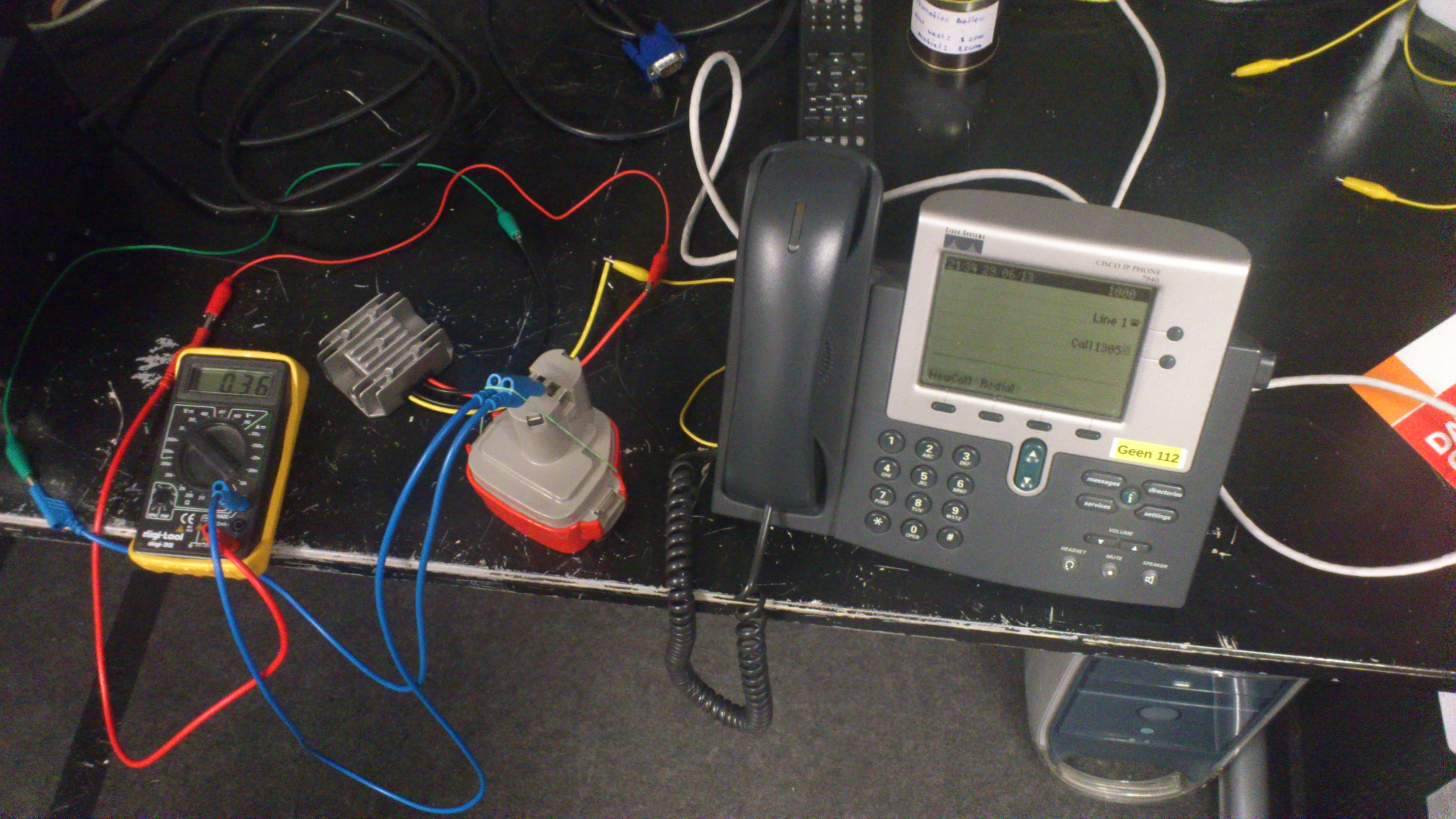
| two Raspberry Pis, step down | drill battery pack | 12.6V[1] | 330mA | 2×2W |
| Cisco CP7940, step up | drill battery pack | 12.6V[1] | 360mA - 450mA | 5W |
| Fritz!box (wifi off), direct | lab power supply | 12V | 360mA (idle) - 440mA (42% - 52%, top ~880mA) |
4.3W - 5.3W |
| 15V | 250mA (idle) | 3.8W | ||
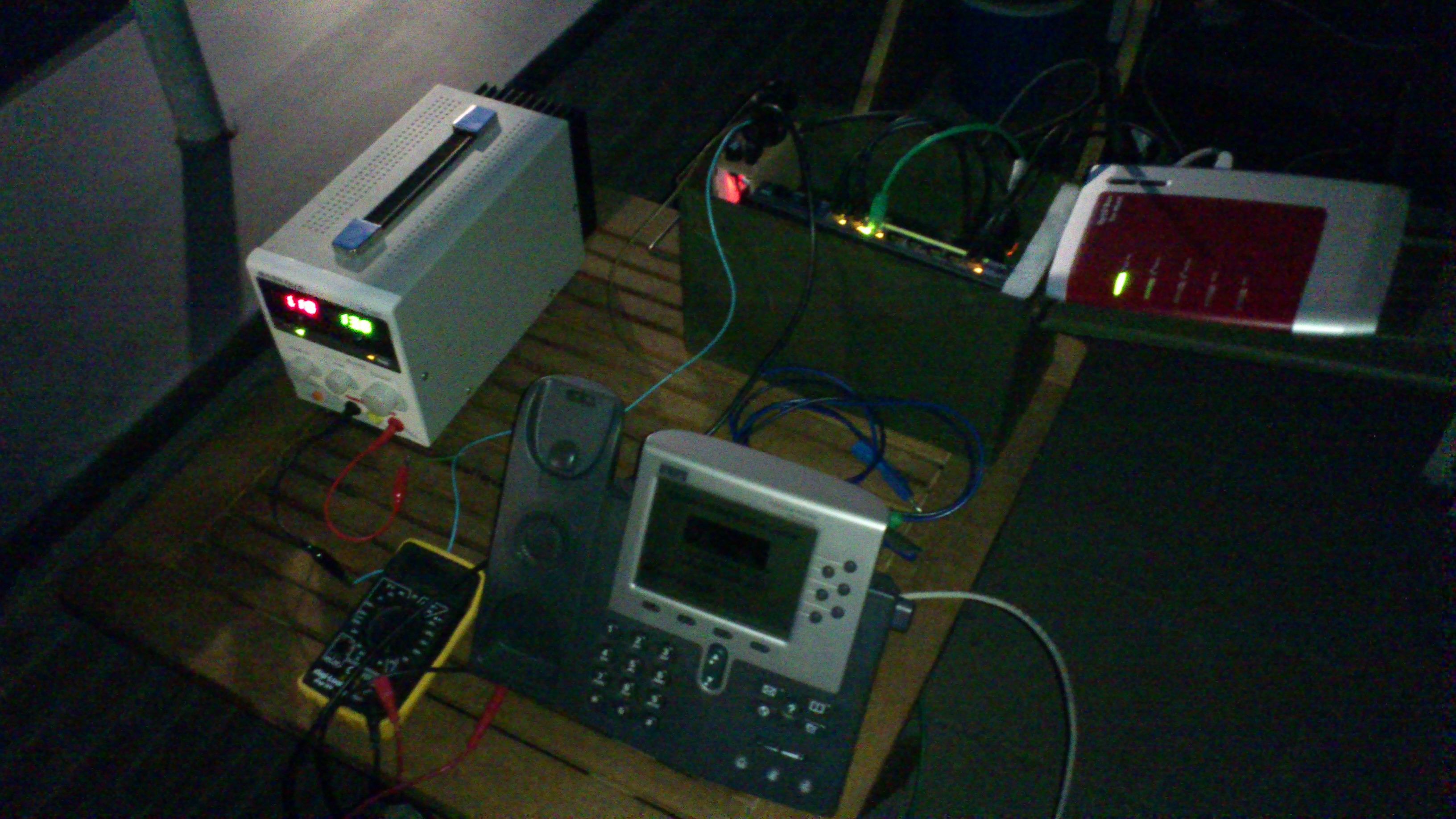
| Netgear GS110TP PoE, step up | lab power supply | 12V | 330mA | 4W |
| Netgear GS110TP PoE + Cisco CP7940, step up |
lab power supply | 12V | 740mA | 9W |
| Complete set: 2 RasPis, Fritz!box, switch, phone + cellphone charging |
lab power supply | 12V | 2000mA | 24W |
| 13.8V | 1600mA | 22W | ||
| cellphone charging | lab power supply | 5W[2] | ||
| A) Netgear, Pi, 7940, Gl.inet | SLA battery | 12V | 12W[3] | |
| B) Netgear, Pi, 7940, Gl.inet, Gigaset | SLA battery | 12V | 13.3W[3] | |
| C) Netgear, Pi, 7940, FritzBox | SLA battery | 12V | 16.3W[3] |
- [1] Approximated by calculating deviation from the lab power supply combined values, which was about 5% off 12V
- [2] Approximated by subtracting all calculated items from the complete setup
- [3] Approximated by just adding up individual items, using Netgear GS110TP PoE, Raspberry Pi, Gl.inet, Siemens Gigaset N510 and/or Fritz!box
solar panel and battery
Did some rough estimations with a 15 Watt solar panel (using a Unified Clear-Sky Solar Prediction Model script): on a good summer day it will yield 240W in 17 hours (slightly below 15 megajoule), and on a clear winter day it will yield 25W in 7 hours (630 kilojoule).
A 12v SLA battery is full with >12.85V, empty with 12.00V (at 25% capacity) and fully depleted at 11.80V. I came to the conclusion that the effective energy is about 9.5×Ah; given a 7Ah battery, this will yield about 66.5Wh.
Given the hardware setups described in the previous paragraph (note that these values are theoretical maximums):
| scenario | battery run time | solar+battery run time (winter/summer) |
|---|---|---|
| A | 5:30h | 7:35h/25:30h |
| B | 5:00h | 6:55h/23:00h |
| C | 4:00h | 5:35h/18:45h |
interesting facts
- Fritz!box has a switching regulator to 5V tested between 5.5V and 15V (drops off at 5.3V idle and elco at power supply segment is rated 16V)
- PoE hack adapter connected pin 1 (white-orange) and pin 3 (white-green) with 22K resistor.
- if the pre-standard CP-79x0 is connected using the PoE adapter hack, the Netgear GS110TP doesn't power, when you unplug it, it will enable power within 5 seconds; plug in, and the phone boots.
- if you configure the administrative VLAN, the phone will fetch a DHCP lease on that VLAN, allowing you to seperately set up dnsmasq on a Raspberry Pi
inventory
- Fritz!Boxes
- 7270 (ADSL2+, 1×USB 2.0, a/b, S0 [FXO], 2×FXS, S0-bus, n×DECT, 4×100Mbit, 2.4GHz or 5GHz, 64MB RAM)
- 7340 (ADSL2+, VDSL, 2×USB 2.0, a/b, S0 [FXO], 2×FXS, n×DECT, 2×Gbit, 2.4GHz or 5GHz, 128MB RAM)
- 7340 (ADSL2+, VDSL, 2×USB 2.0, a/b, S0 [FXO], 2×FXS, S0-bus, n×DECT, 4×100Mbit, 2.4GHz and 5GHz, 512MB RAM)
- DECT phones
- 2×Siemens AL28H
- 2×Siemens A420 (PsychiC has one)
- 2×Philips CD6552B
- 2×Philips CD1302S
- 1×Philips DECT1221S
- 1×Profoon PDX2900
- + what's not yet inventoried at the space
log and ideas
A list of ideas to consider:
- modular 3D insert for different single board computers
- extra network outlet (since a single one is more or less useless)
- float or CC/CV charger, MPPT solar charger
- external antenna mount
- temperature monitor
Here is a log/some steps to reproduce:
get the basics
apt-get install vlan dnsmasq make curl
create and install FreeSWITCH
see https://freeswitch.org/confluence/display/FREESWITCH/Debian#Debian-BuildingFromSource
cd /usr/src
curl https://freeswitch.org/stash/projects/FS/repos/freeswitch/browse/build/Makefile.centos6?raw > Makefile
If you want to compile and install STABLE branch, edit the above Makefile and add " -b v1.4 " just after the word "clone".
make && make install
- (you can kill time by doing the other chapters)
create user 'freeswitch', add it to group 'daemon' and change owner and group of the freeswitch installation
cd /usr/local
adduser --disabled-password  --quiet --system --home /usr/local/freeswitch --gecos "FreeSWITCH Voice Platform" --ingroup daemon freeswitch
chown -R freeswitch:daemon /usr/local/freeswitch/
chmod -R ug=rwX,o= /usr/local/freeswitch/
chmod -R u=rwx,g=rx /usr/local/freeswitch/bin/*
prepare VLAN
modprobe 8021q
lsmod | grep 8021q
echo 8021q >> /etc/modules
vconfig set_name_type DEV_PLUS_VID_NO_PAD
set-up network and VLAN
vi /etc/network/interfaces
auto lo
iface lo inet loopback

auto eth0

# dhcp configuration, used in normal operation (this connects to your internet)
iface eth0 inet dhcp

# static ip configuration, used for stand-alone preconfiguring factory-reset phones
#iface eth0 inet static
#	address 192.168.6.1
#	netmask 255.255.255.0
#	gateway 192.168.6.1

# operational VLAN 11 (pick any), for usage with VoIP
auto eth0.11
iface eth0.11 inet static
    address 192.168.11.1
    netmask 255.255.255.0
    vlan-raw-device eth0
dnsmasq
vi /etc/dnsmasq.conf
# uncomment to enable dhcp server on eth0, used for stand-alone preconfiguring factory-reset phones
#interface=eth0
# operational VLAN 11 (pick any), for usage with VoIP
interface=eth0.11

# Choose different ranges for each (V)LAN
dhcp-range=eth0,192.168.6.50,192.168.6.150,12h
dhcp-range=eth0.11,192.168.11.50,192.168.11.150,12h

# Most likeley not needed
#option:tftp-server
#dhcp-option=66,192.168.6.1
#option:
#dhcp-option=150,192.168.178.16

# Enable dnsmasq's built-in TFTP server to serve config files
enable-tftp

# Set the root directory for files available via FTP.
tftp-root=/srv/tftp
Create the /srv/tftp directory and put the configs and firmwares in it. Here is a config generator you can put in there (sorry, can't provide the firmwares since "I don't have them").
service dnsmasq restart
or
/etc/init.d/dnsmasq restart
toggleconfig script
#!/bin/bash

restart_services()
{
  trap -- SIGHUP SIGINT SIGTERM

  service dnsmasq stop > /dev/null
  #nohup sh -c "invoke-rc.d networking stop; sleep 2; invoke-rc.d networking start"
  invoke-rc.d networking stop > /dev/null
  sleep 2
  invoke-rc.d networking start > /dev/null
  service dnsmasq start > /dev/null

  trap clean_up SIGHUP SIGINT SIGTERM
}

clean_up()
{
  # reset gpio pin and led
  echo "11" > /sys/class/gpio/unexport
  echo 0 > /sys/class/leds/led0/brightness
  echo none > /sys/class/leds/led0/trigger

  echo done
  exit
}

if [ ! -f /etc/dnsmasq.conf.regular ]; then echo "/etc/dnsmasq.conf.regular does not exist"; exit; fi
if [ ! -f /etc/dnsmasq.conf.config ]; then echo "/etc/dnsmasq.conf.config does not exist"; exit; fi
if [ ! -f /etc/network/interfaces.regular ]; then echo "/etc/network/interfaces.regular does not exist"; exit; fi
if [ ! -f /etc/network/interfaces.config ]; then echo "/etc/network/interfaces.config does not exist"; exit; fi

trap clean_up SIGHUP SIGINT SIGTERM

echo "11" > /sys/class/gpio/export
echo "in" > /sys/class/gpio/gpio11/direction

while true; do

  echo "regular mode"
  echo none > /sys/class/leds/led0/trigger

  # regular config files
  cp /etc/dnsmasq.conf.regular /etc/dnsmasq.conf
  cp /etc/network/interfaces.regular /etc/network/interfaces

  restart_services

  while [ `cat /sys/class/gpio/gpio11/value` -gt 0 ]; do
    echo 1 > /sys/class/leds/led0/brightness
    sleep 0.05
    echo 0 > /sys/class/leds/led0/brightness
    sleep 3
  done

  echo "config mode"
  echo "heartbeat" > /sys/class/leds/led0/trigger

  # regular config files
  cp /etc/dnsmasq.conf.config /etc/dnsmasq.conf
  cp /etc/network/interfaces.config /etc/network/interfaces

  restart_services

  while [ `cat /sys/class/gpio/gpio11/value` -le 0 ]; do sleep 3; done

done
preconfigure phone
- Connect the phone directly using a (optionally crosslink) ethernet cable.
- Power the phone, and hold # until the red (mute) light is off and the phone states: "Reset sequence detected"
- type 123456789*0#, and when asked to keep network config, choose 2=no
- once the new firmware is loaded (Freeswitch is not running, so it won't connect), press 'settings' (checkbox button at the bottom right)
- go to Admin. VLAN ID
- type **# to unlock the setting, and press 'edit'
- type in your voice VLAN (11 like the configs say)
- press validate, and save
- dnsmasq and interfaces configs can now be restored (no dhcp on eth0, only eth0.11)
- nohup sh -c "invoke-rc.d networking stop; sleep 2; invoke-rc.d networking start"
todo
- work out 'modus operandi': multiple config files switchable by phone
- work on dual linux config with GPIO hardware switch
- test the fibre ports
- add homeplug as a proof of concept
- design and create (or buy) small-sized float charger (13.8V 2A) with overcurrent protection, if needed
links
Some random links:


